
“As a practical and fashionable way of human-computer interaction, capacitive touch technology has been widely used in various Electronic products, ranging from light switches to tablet computers and touch tables. What follows is a test of how product designers can use their wisdom to design the user interface of the product to be convenient and concise, and at the same time to present the product’s gorgeous appearance, thereby bringing a good user experience.
“
Introduction
As a practical and fashionable way of human-computer interaction, capacitive touch technology has been widely used in various electronic products, ranging from light switches to tablet computers and touch tables. What follows is a test of how product designers can use their wisdom to design the user interface of the product to be convenient and concise, and at the same time to present the product’s gorgeous appearance, thereby bringing a good user experience.
Because of the friendly interface, the LED Display can reflect the touch position information in real time, and is widely used in the design of capacitive touch products. This design uses a large number of LEDs to realize the special effects of breathing lights and track lights, which can provide design references for products with adjustment functions such as lighting, volume, and temperature.
Texas Instruments’ MSP430 series microcontrollers are famous for their low power consumption and richness of peripheral modules. For capacitive touch applications, the PIN RO capacitive touch detection method of MSP430 supports the direct connection of the IO port to the detection electrode without any peripheral devices. The circuit design is simplified, and the MSP430G2XX5 used in this design document supports up to 32 IO ports and can drive more than 24 LED lights to achieve the ideal display effect.
1. Capacitive touch wheel implementation scheme
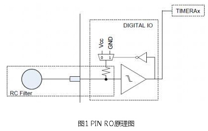
The MSP430 capacitive touch wheel scheme completes the capacitance detection of 4 channels through 4 IO ports, and with special electrode patterns, the design of the wheel can be realized.
1.1 The principle of capacitive touch
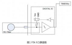
MSP430 supports a variety of capacitive touch detection methods according to different models, including RC oscillation, comparator, and PIN RO. This design uses the PIN Relaxation Oscillator method. , an inverter, and a resistor. The oscillation signal is converted into a pulse signal through the Schmitt trigger, and then fed back to the RC circuit through the inverter. The output of the Schmitt trigger is counted through Timer_A, and then set The measurement window Gate obtains the counted result. When the finger touches the electrode, the C on the electrode changes, resulting in a change in the oscillation frequency. In this way, different counting results can be obtained in a fixed-length measurement window. Once the difference exceeds the threshold, a touch event can be triggered by combining a certain filtering algorithm. .
1.2 Runner algorithm
The four button electrodes are crossed in a zigzag manner as shown in Figure 2 to form an electrode of a runner. The size of the runner can be appropriately scaled according to the needs of product design. The graphic design in Figure 2 is suitable for a runner with a diameter of about 30mm.
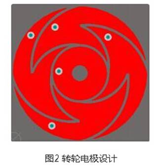
When the user operates on the wheel, the electrode at the corresponding position of the finger will obtain the highest signal value, the channel adjacent to the finger will have a relatively high signal value, and the channel farthest from the finger will detect the smallest signal value, as shown in the figure 3 shows:
At this time, the position of the finger on the wheel or slider can be calculated by using the different signal values on different channels. The location calculation steps are as follows:
a. Use the sorting method to find the electrode with the largest signal among the 4 electrodes
index = Dominant_Element(groupOfElements, &measCnt[0]);
b. Add the signal of this electrode found to the signal of the adjacent electrode
position = measCnt[index] + measCnt[index+1] + measCnt[index-1];
If the added result is greater than the threshold, it is considered that a touch event has occurred, and the subsequent position calculation is continued. The reason for adding the front and back signals is that the finger may be in the middle of the two electrodes during the operation, so the signals obtained on the two electrodes will not be very high, and the signals need to be added before they can be compared with the threshold.
c. When calculating the position coordinates, first obtain an approximate position according to the filtered index value, and then correct it according to the signal strength of the adjacent electrodes of the index to obtain the final coordinate value
position = index*(groupOfElements->points/groupOfElements->numElements);
position += (groupOfElements->points/groupOfElements->numElements)/2;
position += (measCnt[index+1]*(groupOfElements->points/groupOfElements->numElements))/100;
position -= (measCnt[index-1]*(groupOfElements->points/groupOfElements->numElements))/100;
d. For the case where the index is 0 or 3, the code needs to be processed separately, but the calculation method is the same as the above.
The resolution of the wheel here, that is, how many segments the wheel is divided into is set according to the points. Assuming that the user only needs to distinguish 24 positions, the points can be set to 24, of course, it can also be set to 64, 128, or even Higher, it depends on the size of the runner, the design of the electrode pattern and the number of electrodes. For example, if a high precision like 1024 is required, the number of electrodes needs to be increased from 4 to 8 or more.
2. Implementation of LED PWM drive scheme
To achieve the effect of LED breathing, the LED is required to perform PWM dimming, and to achieve the effect of track lights, each LED must be independently PWM controlled.
Since this application uses 24 LED lights, it needs 24 channels of PWM output control. MSP430G2955 has 32 IO ports, which are enough to support 24 channels of software PWM output through the IO port and the TIMER timer.
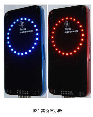
3. Design example
This example uses Texas Instruments MSP430G2955 to complete capacitive touch detection through 6 IOs, 24 IOs drive 24 LEDs, and a communication port is reserved. The design example is shown in Figure 4
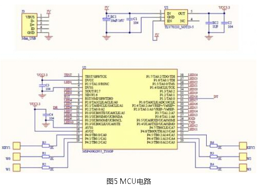
3.1 Circuit Design
The schematic design is shown in Figure 4. The MCU supplies power to VCC through a 5V to 3.3V LDO. The purpose of using the LDO is to ensure the stability of the power supply, so that the touch circuit will not generate excessive signal deviation due to the noise of the power supply when detecting signals. . The resistors on the electrodes are used as ESD protection devices, which can be omitted if the product structure is properly designed. A UART port is reserved in the circuit to communicate with the main control system.
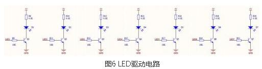
The LED driver circuit is shown in Figure 5. Since the current of each LED is about 10mA, if 24 LEDs are on at the same time, there will be 240mA, which cannot be directly driven through the MCU IO port. Add a triode and a current limiting resistor to each LED to achieve 24-way LED control.
3.2 Code Design
3.2.1 LED driver
Before writing the code to control the LED lighting sequence, first define the specifications related to the PWM output:
The PWM output duty cycle is set to 50%.
The frequency is 5KHz, and the brightness level is divided into 24 levels. When level 0, the LED is turned off, and when it is 23, it is the brightest.
Use 2 TIMER to control the PWM output.
TIMERA0 interrupt frequency is 24X5KHz=120KHz.
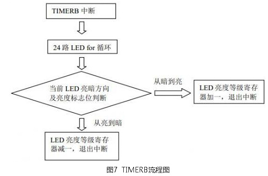
The TIMERB interrupt interval is set to 10ms, and the LED brightness level is changed in TIMERB.
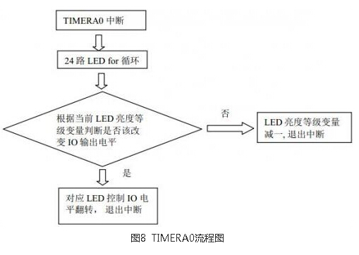
Through the interrupt coordination of two TIMERs, the control of 24 independent PWM outputs can be completed. When a touch event occurs, the brightness level of the corresponding LED is assigned according to the touch position, and then the brightness level is slowly reduced to zero during the interruption of TIMERB, so that the corresponding LED can be gradually dimmed after the finger leaves the electrode. Effect.
The program flow charts in the two TIMER interrupts are as shown in Figure 7 and Figure 8
3.2.2 Wheels
The capacitive touch software library of Texas Instruments supports the signal detection of capacitive buttons and the calculation of the coordinates of the wheel. The position value of the current touch event can be obtained through the configuration of the relevant parameters of the software library and the call of the function. You can refer to the touch button software library of Texas Instruments. Get a detailed introduction.
When the user performs a sliding operation on the wheel, the LED track display should be that N lights are lit at the same time, the light at the finger position is the brightest, and the lights on the track that have been swiped before are darker than the other, and the value of N is determined by the operation. The speed of the user’s sliding is determined. If the sliding speed is fast enough, the 24 LED lights will be lit at the same time, but the brightness is different.
There is a problem when the sliding operation is very fast. The scanning period of the capacitive button cannot keep up with the sliding speed, resulting in the change of the coordinates is not continuous, and the result is that the trajectory of the LED is not continuous. not lit. In order to solve this problem, it is necessary to add an interpolation algorithm after the calculation of the coordinates of the runner. When the user operates too fast, the missing coordinates are supplemented, so that the trajectory of the LED is continuous.
The interpolation method can determine whether to perform interpolation by comparing the current position and the previous position. Here, an interpolation threshold InterpolationThreshold needs to be set. When the position jumping distance exceeds the threshold, the interpolation will not be performed, and a misoperation will occur anyway.
if((WheelPosition-LastPosition)for (j=1;jSetLightLevel(LastPosition+j);
In addition, two special cases need to be handled, and the forward and reverse sliding operations pass through the wheel coordinate 0 point.
4. Summary
This paper introduces the use of MSP430G series single chip to realize capacitive touch wheel and 24 independent PWM output LED control scheme, which has great use value in some occasions that require low-cost product design and control of various LED special effects.
The Links: LM260WU2-SLA1 FS75R12KE3


