
Analysis on the characteristics, parameters and selection method of EMC protection device TVS
“The transient interference of voltage and current is the main cause of damage to Electronic circuits and equipment, which often brings immeasurable losses to people. These disturbances usually come from the start-stop operation of power equipment, the instability of the AC power grid, lightning disturbance and electrostatic discharge, etc. Transient disturbances are almost ubiquitous and occur all the time, making people feel unavoidable. Fortunately, the emergence of a high-efficiency circuit protection device TVS makes the transient interference effectively suppressed.
“
The transient interference of voltage and current is the main cause of damage to electronic circuits and equipment, which often brings immeasurable losses to people. These disturbances usually come from the start-stop operation of power equipment, the instability of the AC power grid, lightning disturbance and electrostatic discharge, etc. Transient disturbances are almost ubiquitous and occur all the time, making people feel unavoidable. Fortunately, the emergence of a high-efficiency circuit protection device, TVS, has effectively suppressed transient interference.
TVS (TRANSIENT VOLTAGE SUPPRESSOR) or transient voltage suppression diode is a new product developed on the basis of Zener tube technology. Its circuit symbol is the same as that of an ordinary Zener diode, and its shape is the same as that of an ordinary diode. When both ends of the TVS tube are subjected to an instantaneous high-energy shock, it can make it at a very high speed (up to 1*10-12 seconds). The impedance drops suddenly, and at the same time absorbs a large current, clamping the voltage between its two ends at a predetermined value, thus ensuring that the subsequent circuit components are not damaged by the impact of transient high energy.
Characteristics and Parameters of TVS

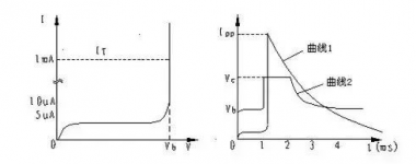
Figure 1 TVS characteristic curve
Features of TVS
If the characteristics of TVS are observed with a grapher, the waveform shown on the left in Figure 1 can be obtained. If you look at this curve alone, there is no difference between the breakdown characteristics of TVS tube and ordinary Zener tube, which is a typical PN junction avalanche device.
However, this curve only reflects a part of TVS characteristics, and the characteristic curve shown on the right must be supplemented to reflect all the characteristics of TVS. This is the current and voltage waveforms observed on the dual trace oscilloscope when the TVS tube is subjected to a large current impact.
Curve 1 in the figure is the current waveform in the TVS tube, which means that the current flowing through the TVS tube suddenly rises from 1mA to the peak value, and then decreases exponentially. The reason for this current shock may be lightning strike, overvoltage, etc. Curve 2 is the waveform of the voltage at both ends of the TVS tube, which means that when the current in the TVS suddenly rises, the voltage at both ends of the TVS also rises, but the maximum only rises to the VC value, which is slightly larger than the breakdown voltage VBR. The circuit elements at the back act as protection.
Parameters of TVS
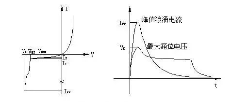
Figure 2 TVS characteristics and parameters
A. Breakdown voltage (VBR): The impedance of the TVS suddenly decreases at this time, and it is in the state of avalanche breakdown.
B. Test Current (IT): The breakdown voltage VBR of TVS is measured at this current. Under normal circumstances, IT takes 1MA.
C. Reverse displacement voltage (VR WM): the maximum rated DC working voltage of TVS, when the voltage across the TVS continues to rise, the TVS will be in a high resistance state.
D. Maximum Reverse Leakage Current (IR): The maximum current flowing through the TVS measured at the operating voltage.
E. Maximum peak pulse current (IPP): The maximum surge current that TVS allows to flow, which reflects the surge suppression capability of TVS.
F. Maximum clamping voltage (VC): When the TVS tube is subjected to transient high-energy shock, a large current flows in the tube, the peak value is IPP, and the terminal voltage does not rise from the VRWM value to the VC value, thus achieving protection. effect. After the surge, the IPP decays exponentially with time. When the decay reaches a certain value, the voltage across the TVS begins to drop from VC and returns to its original state. The ratio of the maximum clamping voltage VC to the breakdown voltage VBR is called the clamping factor Cf, which is expressed as Cf=VC/VBR, and the general clamping factor is only 1.2 to 1.4.
G. Peak pulse power (PP): PP is divided into four types according to the different TVS of peak pulse power, including 500W, 600W, 1500W and 5000W. Maximum peak pulse power: The maximum peak pulse power is: PN=VC・IPP. Obviously, the greater the maximum peak pulse power, the greater the peak pulse current IPP that the TVS can withstand; on the other hand, after the rated peak pulse power PP is determined, the peak pulse current IPP that the TVS can withstand increases with the maximum clamping voltage VC. decrease and increase. The maximum allowable pulse power of TVS is not only related to the peak pulse current and clamping voltage, but also related to the pulse shape, pulse duration and ambient temperature.
The instantaneous pulse peak value that TVS can withstand can reach hundreds of amperes, and its clamping response time is only 1*10-12 seconds; the forward surge current allowed by TVS, under the condition of 25℃, 1/120 seconds, Also up to 50-200 amps. Generally speaking, the transient pulses that TVS can withstand are non-repetitive pulses. In practical applications, repetitive pulses may appear in the circuit.
TVS devices specify that the pulse repetition rate ratio (the ratio of pulse duration to pause time) is 0.01%. If this condition is not met, the accumulation of pulse power may burn the TVS. Circuit designers should take note of this. The work of TVS is reliable, even if it is subjected to high-energy shocks of non-repetitive large pulses for a long time, there will be no “aging” problem. The test proves that the maximum allowable pulse power of TVS is still more than 80% of the original value after 10,000 pulses.
How to choose TVS
1. Determine the DC voltage or continuous working voltage of the circuit to be protected. If it is AC, the maximum value should be calculated, that is, the effective value*1.414.
2. The reverse displacement voltage of the TVS is the working voltage (VRWM) – select the VRWM of the TVS to be equal to or greater than the operating voltage specified in step 1 above. This ensures that the current absorbed by the TVS is negligible under normal operating conditions. If the voltage specified in step 1 is higher than the VRWM of the TVS, the TVS will absorb a large amount of leakage current and be in avalanche breakdown state, thus affecting the work of the circuit.
3. Maximum peak pulse power: Determine the interference pulse situation of the circuit, and determine the TVS peak pulse power that can effectively suppress the interference according to the waveform and pulse duration of the interference pulse.
4. The maximum clamping voltage (VC) of the selected TVS should be lower than the maximum withstand voltage allowed by the protected circuit.
5. Unipolar or Bipolar – There is often a misconception that bidirectional TVS is used to suppress reverse surge pulses, which is not the case. Bidirectional TVS is used for alternating current or from positive and negative bidirectional pulses. TVS is also sometimes used to reduce capacitance. If the circuit has only forward level signals, then a unidirectional TVS is sufficient. The TVS operates as follows: during forward surge, TVS is in reverse avalanche breakdown state; during reverse surge, TVS conducts like a forward-biased diode and absorbs surge energy. This is not the case in low capacitance circuits. A bidirectional TVS should be used to protect low-capacitance devices in the circuit from reverse surges.
6. If you know the more accurate inrush current IPP, you can use VC to determine its power. If the approximate range of power cannot be determined, generally speaking, it is better to choose a larger power.
The Links: FZ800R16KF4 CM600HA-12H


