
Low solar energy capture efficiency?It seems that you did not choose the right front-end management system
[Guide]Solar energy seems to be “free” renewable energy, but in fact, to transform impact electrons into usable resources, rigorous design schemes, advanced Electronic equipment and sophisticated battery charging/discharging management systems are required .
Solar energy is widely used, mainly divided into the following three scenarios:
● Data recording and energy harvesting system of the Internet of Things, the power is in the range of milliwatts, and the output is low-voltage DC;
● As the main power supply, backup power supply or supplementary power supply for home or remote devices, it can usually be used for power transmission, the power is between 100 watts and kilowatts, and the output is AC line voltage;
● The power generation system, which is part of the power grid, is fixed in place, with a power of hundreds of thousands of kilowatts, and an output of thousands of volts of alternating current.
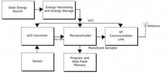
Although energy harvesting applications may ignore many user-oriented modules such as displays, solar installations with wireless links still require a large number of additional functions, as shown in Figure 1. From a big point of view, the power subsystem may be just a small design, but in fact it is not.
It has the following functions and modules: a front end that connects to solar cells and captures energy from it; a power management function that directs energy to a storage unit (battery or supercapacitor), and a power load management module that controls the extraction of energy from the storage unit. The system first captures the available energy (joules), and then releases it in the form of power (watts) to meet the load demand.[功率是运行负载所需的能量利用率;但以能量(即功率对时间的积分)的形式被捕获。]

Figure 1: For the Internet of Things, a complete solar power system is composed of many functional blocks; but when used as a backup or backup power source, functional blocks (such as sensors and RF links) are not required (Source: Mouser Electronics)
In fact, we need to understand how much energy can be extracted from the sun. The average solar radiation reaching the top of the earth’s atmosphere is about 1kW/m2 or 0.1W/cm2.
Even on a sunny day, only a small part of the radiation can pass through the atmosphere to reach the ground, and the efficiency of solar cells is only 15-20%. Therefore, an optimistic estimate is that the usable energy released by solar cells is about 10mW/cm2. Coupled with the loss of capture, storage, and output conversion, the usable energy released by solar cells per square centimeter is quite low, which does not include the effects of night, cloudy, seasonal radiation, and latitude and longitude.
It can be seen from this that, especially in mW acquisition applications (no need to worry about I2R loss), it is very necessary to minimize the loss of the entire solar power generation system. This optimization is particularly challenging for the front end, where the power output of the solar cell must be extracted and collected. This is because any loss or inefficiency cannot be made up after this, and the solar energy that hits will also disappear forever.
Improve efficiency through power point tracking
Most traditional energy sources (power supplies) perform relatively well as current or voltage sources with fixed parameters (such as internal resistance), while solar cells have unusual characteristics. It is necessary to understand these characteristics in order to capture as much of their output as possible. The designer’s goal is to obtain the maximum power from the solar cell, regardless of the output voltage and current, because these two quantities will change with changes in working conditions.
Under a given set of working conditions, there will be a unique “working point” called the maximum power point (MPP), at which the battery output power (ie V × I) is at its maximum. To extract power, the battery load (that is, the resistance of the connected circuit) must match the characteristic resistance of the battery.
This matching situation is similar to the need to match any power supply to the load to achieve maximum power transmission, such as between the output impedance of a power amplifier and the load antenna, or between the antenna and the RF front end. In most cases, the source impedance and load impedance parameters are relatively constant, so it can be regarded as a fixed circuit (in some applications, especially high-performance radio frequency applications, it is necessary to take into account self-heating and environmental conditions, Some parameters will change with temperature).
However, the working conditions of solar cells are never constant and change repeatedly due to changes in lighting, battery temperature, battery life, and other factors. Therefore, the solar system must dynamically change the battery load to obtain maximum efficiency. This technique is called Maximum Power Point Tracking (MPPT). Effective MPPT can be achieved through traditional graphs of current-voltage and power-voltage relationships with resistive load lines and maximum power lines, as shown in Figure 2a and Figure 2b.


Figure 2: a) and b) respectively show the complex photovoltaic array current-voltage and power-voltage curves; load line and maximum power point are the key to finding the highest efficiency (from the Power Electronics, Drive and Machine Research Group of Newcastle University)
(Source: Low-cost MPPT algorithm from photovoltaic applications: Photovoltaic pump case study, slides 5 and 6)
MPPT can be achieved in several ways:
For the “disturbance observation” method, the impedance of the front-end circuit comes from “disturbance”, so the output needs to be monitored; if the power increases, continue to adjust the voltage in the same direction until the power no longer increases. This is the standard method for finding the maximum/minimum value for many optimization schemes.
Other methods include determining the internal parameters of the battery by using scanning current or voltage drive to manipulate the transconductance of the battery.
Each method has advantages and disadvantages, such as excessive oscillation or “swing” when seeking MPP, or sub-optimal performance when trying to react to relatively rapid changes in MPP.
MPPT implementation method
No matter which MPPT algorithm is selected, it can be realized in the form of hardware through a dedicated IC, or in the form of firmware (software) as a part of the system microcontroller programming. Although the latter option provides great flexibility and the ability to fine-tune or even change the MPPT algorithm, it may also increase the system burden. Therefore, compared with fixed-function ICs, higher-speed, more power-consuming processors are required. As with almost all engineering decisions, there are trade-offs when choosing an MPPT algorithm, and the main cost or power increment threshold must also be considered.
For small acquisition systems, it is generally more cost-effective and efficient to implement a single MPPT through a dedicated IC; for multi-element arrays distributed in a large area (or even only a few square meters), it may be necessary to provide a separate unit for each unit partition. MPPT, because each unit and partition may have different characteristics. Therefore, according to the size of the solar array, the power level and the required flexibility (or no consideration at all), choose whether to use a front-end IC with a dedicated MPPT, an acquisition subsystem IC with an embedded MPPT, or a firmware-based MPPT processor.
In addition, fully programmable controllers can be used to further enhance complexity and flexibility, such as the TMDSHVMPPTKIT high-voltage isolation solar MPPT development kit from Texas Instruments. This complete evaluation board (Figure 4) is used for high-power systems with an input of 200-300VDC and a power of up to 500W. It uses the Piccolo F28035 processor in the C2000 series, and has a two-phase interleaved boost stage and a half-bridge resonance LLC isolation stage for maximum power point tracking. These two levels can be digitally controlled by a single MCU. Designers can select MPPT through incremental conductance method or perturbation observation method, and then test the effectiveness of these two methods in the application.

Figure 3: As a fully programmable solution, Texas Instruments TMDSHVMPPTKIT is a high-voltage isolated solar development kit with MPPT algorithm. It uses Piccolo F28035 processor and can provide 500W of power
(Source: http://www.ti.com/tool/TMDSHVMPPTKIT)
This kit has a built-in USB JTAG emulation function, so no external hardware is required, and it also includes a graphical user interface that can be quickly started. All hardware and software are fully documented and open source for design use. This evaluation board makes up for the deficiencies of TI TMSHV1PHINVKIT; their combination forms a complete DC-AC solar powered inverter system.
Medium-scale MPPT can use devices such as Microchip Technology PIC16F1503 MCU. The IC is one of a series of enhanced core devices, with peripheral equipment such as NCO (Numerical Control Oscillator), CWG (Complementary Waveform Generator) or CLC (Configurable Logic Unit). Microchip provides detailed information in its application notes, including MPPT flowcharts and related code modules[参考文献1(AN1467)和2(AN1521)]; Both can be used with PIC devices, and the flowchart can be used alone as a guide for any processor programming work.
For electronic circuits, from small-scale Internet of Things to large-scale backup, and even main power supply, solar energy is very attractive due to its free and inexhaustible advantages. However, the currently available solar energy is only a small part, so any design must pay attention to its front-end efficiency (such as the MPPT problem), so that this method is economically reasonable and technically feasible. Of course, whether the designer chooses a dedicated front-end IC or a fully programmable, processor-based design, it all depends on the size of the solar array, physical layout, required degree of modularity, and cost.
Reference resources
[1] AN1467, “High Power CC/CV. Battery Charger with Inverted SEPIC (Zeta) Topology, Microchip Technology
[2] AN1521, “A Practical Guide to Implementing MPPT Algorithms for Solar Panels”, Microchip Technology
[3] High Voltage Isolated Solar MPPT Developer’s Kit, Texas Instruments
[4] TIDU404, digitally controlled high voltage solar MPPT DC-DC converter, Texas Instruments
[5] Ultra-low power consumption meets energy harvesting needs-white paper, Texas Instruments
[6] C2000™ Solar Inverter Development Kit, Texas Instruments
[7] Power Management IC Development Tool High Vltg Independent Solar MPPT Development Kit, Mouser Electronics
[8] Solar energy harvesting technology, Mouser Electronics
[9] Low-cost MPPT Algorithms for Photovoltaic Applications: Case Study of Photovoltaic Pumps, Power Electronics, Drives and Machinery Research Group, Newcastle University
Source: Mouser Electronics, Original: Bill Schweber
The Links: LQ038Q7DB03R 2MBI600VD-060-50


