In-depth analysis of BridgeSwitch motor driver solutions
“The control of motor speed and direction requires the use of the operating system used, as well as different technologies and circuits depending on the type of motor and the needs of different applications. The purpose of the motor controller is to be able to act on the motor manually or automatically (start-stop, lead-reversal, speed, torsion and protection against voltage overload functions). BLDC motors have many advantages over traditional motors.
“
Author: Maurizio Di Paolo Emilio
The electric motor market is experiencing significant growth in the number of units required each year. All general purpose electric motors will switch to brushless DC solutions (BLDC), which represent a large part of the overall investment market. Also, there will be many applications already installed on boats or about to start using brushless DC motors, such as compressor pumps or industrial pumps for refrigeration, dishwashers or washing machines. This is a strong growth market (Figure 1).
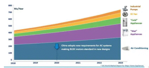
Figure 1: Evolution of the BLDC Motor Market[来源:Power Integrations]
The control of motor speed and direction requires the use of the operating system used, as well as different technologies and circuits depending on the type of motor and the needs of different applications. The purpose of the motor controller is to be able to act on the motor manually or automatically (start-stop, lead-reversal, speed, torsion and protection against voltage overload functions). BLDC motors have many advantages over traditional motors.
Typically, they offer 15% to 20% higher efficiency; requiring less maintenance as they are brushless and offer a flat torque curve at all rated speeds. Recent developments in semiconductor technology, improvements in permanent magnets, and growing demand for higher efficiency have led to the replacement of brushed motors with BLDCs in many applications. BLDC motors can have single-phase, two-phase and three-phase configurations; the most common is three-phase one-phase. The number of phases corresponds to the number of windings on the stator, while the rotor poles can be in any pair depending on the application.
The driver is the basic element of BLDC control. It is a power amplifier that produces a voltage output to drive the high-current high-side and low-side IGBT gates of an H-bridge circuit.
“In choosing the right motor driver, three parameters are important: the package, the continuous current flowing through the motor windings, and the thermal specification,” said Cristian Ionescu-Catrina, senior product marketing manager at Power Integrations.
To meet the huge future demand, Power Integrations is showcasing a new BridgeSwitch family at Embedded World for BLDC engines up to 400 W. This high-voltage half-bridge motor is 99.2% efficient, requires no heat sink, and reduces the time and expense of software certification.
The excellent efficiency combined with the distributed cooling structure of the IHB drives reduces the weight and cost of the system. An integrated non-destructive current detection system, bus voltage detection circuit and system-wide thermal detection circuit make this family of devices ideal for BLDC motors used in home appliances.
BridgeSwitch solutions feature advanced high-side and low-side FREDFETs (Fast Recovery Diode Field Effect Transistors) and integrated lossless current sensing.
FREDFETs are connected in a half-bridge configuration, where the diode structure (ultra-soft and ultra-fast recovery) makes them ideal for hard-switching inverter-based motor drives.
The FREDFETs used in BridgeSwitch ICs integrate fast, extremely smooth intrinsic reset diodes (body diodes). The result is greatly reduced losses during switching and reduced noise levels, thereby simplifying the electromagnetic compatibility of the overall system.
The new 400W BRD1167 and BRD1267 BridgeSwitch ICs deliver up to 1.33 A continuous RMS phase current and 11.5 A FREDFET DC output current. Like the rest of the BridgeSwitch family, they are self-powered and housed in an InSOP-24C surface mount package. These devices can drive single-phase or multi-phase high voltage, synchronous or asynchronous motors, and support all popular MCUs and motor control algorithms. All BridgeSwitch ICs feature overcurrent, over/undervoltage and thermal protection, simplifying IEC 60335 and 60730 certification, saving time and cost.
“In air conditioning fans, people want to integrate the inverter PCB into the motor. The size of the PCB is very small. Often, for this type of application, customers start using external heat sinks. We can eliminate the heat sink, and reduce the cost. This becomes even more pronounced for high-current applications such as air conditioning exteriors, drying fans or refrigerator compressors,” says Christian Inescu Katrina.
“The hot spot where the heat is concentrated is in the FREDFET,” Christian continued. “That switch is very fast, and the current and voltage are very high. Right below the FREDFET, we put two exposed pads. By placing these exposed The pads are connected to the PCB and we can dissipate the heat evenly.”
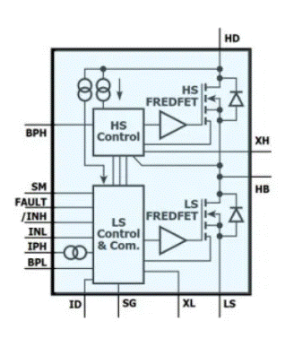
Figure 2: Block diagram of the BRD1167/1267[来源:Power Integrations]
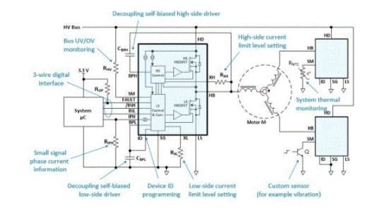
Figure 3: Typical BridgeSwitch three-phase inverter architecture[来源:电源集成]
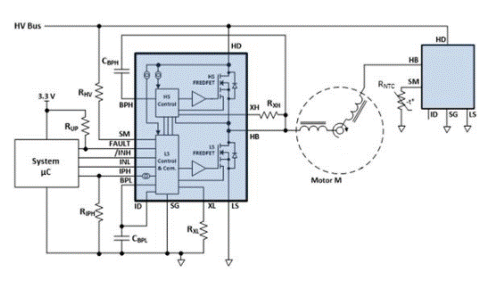
Figure 4: Single Phase Application[来源:电源集成]
Each BridgeSwitch device can be configured with different high-side and low-side current limits, eliminating the need for a microcontroller and external circuitry to protect the system from open circuit conditions or shorted motor windings.
BridgeSwitch devices are internally self-powered and support commutation PWM frequencies up to 20 kHz. To ensure that the supply voltage across the bypass low-side (BPL) pin capacitor and the bypass high-side (BPH) pin capacitor is sufficiently large when the inverter starts up, the system microcontroller (MCU) should follow the recommended power-up sequence shown in Fig. 5 in.
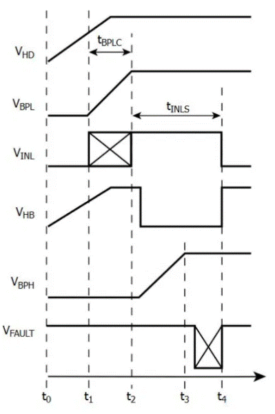
Figure 5: Recommended power-up sequence with self-powered operation[来源:电源集成]
The bypass low pin capacitor CBPL, the BPL pin charging current ICH1(LS) and the bypass low pin voltage VBPL determine the charging time tBPLC from time point t1. The system MCU manages the power-up sequence by turning on and off the low-side power FREDFET at time point t2 and duration tINLS.
The BRD116X device supports discrete low-side FREDFET current sensing through an external current sense resistor in series with the LS pin, as shown in Figure 6. The voltage VSHUNT is a direct representation of the motor winding current IMOTOR. Resistors R1 and R2 set the gain of the external amplifier U1. Resistors R3, C1, C2 and C3 provide noise filtering. Resistor R4 adds the DC offset VOFFSET to the output signal VOP of amplifier U1 (Figure 6).
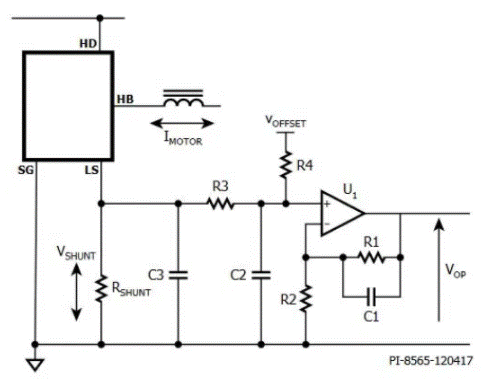
Figure 6: Example circuit for external current sensing[来源:电源集成]
Power Integrations’ new 400W BridgeSwitch solution will support applications with higher RMS current and thermal requirements.
The Links: 6MBP75RS120 LTM201M1-L01


