
“In the instrumentation system, it is often necessary to convert the continuously changing analog quantities detected, such as temperature, pressure, flow, speed, light intensity, etc., into discrete digital quantities before they can be input into the computer for processing. These analog quantities are converted into electrical signals (usually voltage signals) by sensors, and after being amplified by an amplifier, they need to undergo certain processing to become digital quantities. The equipment that realizes the conversion from analog to digital is usually called analog-to-digital converter (ADC), abbreviated as A/D.
“
In the instrumentation system, it is often necessary to convert the continuously changing analog quantities detected, such as temperature, pressure, flow, speed, light intensity, etc., into discrete digital quantities before they can be input into the computer for processing. These analog quantities are converted into electrical signals (usually voltage signals) by sensors, and after being amplified by an amplifier, they need to undergo certain processing to become digital quantities. The equipment that realizes the conversion from analog to digital is usually called analog-to-digital converter (ADC), abbreviated as A/D.
Under normal circumstances, A/D conversion generally involves four processes: sampling, holding, quantization, and encoding.
Sample and hold
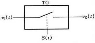
Sampling is the conversion of an analog quantity that changes continuously with time into a time-discrete analog quantity. A schematic diagram of the sampling process is shown in Figure 11.8.1. Figure (a) shows the structure of the sampling circuit, in which the transmission gate is controlled by the sampling signal S

Figure 11.8.1 Sampling circuit structure (a)
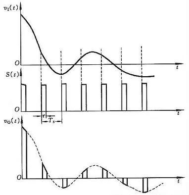
Figure 11.8.1 Signal waveform in the sampling circuit (b)
Through analysis, it can be seen that the higher the frequency of the sampled signal S
Sampling theorem: suppose the frequency of the sampling signal S
It takes a certain amount of time to convert the analog signal obtained by the sampling circuit into a digital signal each time. In order to provide a stable value for the subsequent quantization and encoding process, the analog signal obtained each time must be maintained by the holding circuit for a period of time.
The sampling and holding process is often completed at the same time through a sample-and-hold circuit. The principle diagram and output waveform of the sample-and-hold circuit are shown in Figure 11.8.2.
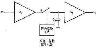
Figure 11.8.2 Schematic diagram of sample-hold circuit
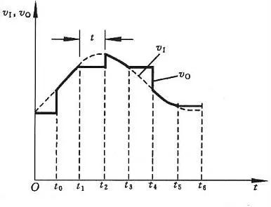
Figure 11.8.2 Sample-and-hold circuit waveform diagram
The circuit is composed of input amplifier A1, output amplifier A2, holding capacitor CH and switch drive circuit. The circuit requires A1 to have a high input impedance to reduce the impact on the input signal source. In order to make the charge stored in the hold phase CH difficult to discharge, A2 should also have a higher input impedance, and A2 should also have a low output impedance, so that the load capacity of the circuit can be improved. Generally, AV1・AV2=1 in the circuit is also required.
Now use Figure 11.8.2 to analyze the working principle of the sample-and-hold circuit. At t=t0, the switch S is closed and the capacitor is quickly charged. Since AV1·AV2=1, v0=vI, and the sampling period is the time interval between t0 and t1. S is disconnected at t=t1. If the input impedance of A2 is infinite and S is an ideal switch, it can be considered that the capacitor CH has no discharge circuit and the voltage at both ends remains unchanged at v0. The flat section from t1 to t2 in Figure 11.8.2(b) is the holding phase .
The sample-and-hold circuit consists of a variety of types of monolithic integrated circuit products. For example, there are AD585 and AD684 for bipolar process; AD1154 and SHC76 for hybrid process.
Quantization and coding
The digital signal is not only discrete in time, but also discontinuous in amplitude. The size of any one digital quantity can only be an integer multiple of a certain specified minimum quantity unit. In order to convert an analog signal to a digital quantity, during the A/D conversion process, the output voltage of the sample-and-hold circuit must be normalized to the corresponding discrete level in a certain approximate manner. This conversion process is called numerical value. Quantification, referred to as quantification. The quantized value finally needs to be expressed with a code through the encoding process. The code obtained after encoding is the digital quantity output by the A/D converter.
The smallest quantity unit taken in the quantization process is called the quantization unit, which is represented by △. It is the analog quantity corresponding to when the lowest bit of the digital signal is 1, that is, 1LSB.
In the quantization process, because the sampled voltage is not necessarily divisible by △, there is inevitably an error before and after quantization. This error is called quantization error and is represented by ε. The quantization error is a principle error, and it cannot be eliminated. The more the number of bits of the A/D converter, the smaller the difference between the discrete levels, and the smaller the quantization error.
The quantization process often uses two approximate quantization methods: only rounding quantization and rounding quantization.
1. Only round off the quantization method
Take a 3-bit A/D converter as an example. Set the input signal v1’s range of change from 0 to 8V. When the quantization method is not rounded only, take △=1V. The part of the quantization that is not enough for the quantization unit is discarded. For example, the value is 0 to The analog voltage between 1V is regarded as 0△, which is represented by the binary number 000, and the analog voltage between 1 and 2V is regarded as 1△, which is represented by the binary number 001…The maximum error of this quantization method is △.
2. Rounding quantification method
If the rounding quantization method is adopted, the quantization unit △=8V/15 is adopted. The quantization process will discard less than half of the quantization unit, and the part equal to or greater than half of the quantization unit will be processed as one quantization unit. It treats all analog voltages with a value between 0~8V/15 as 0△, which is represented by binary 000, while the analog voltage with a value between 8V/15~24V/15 is regarded as 1△ and uses binary numbers. 001 means wait.
3. Compare
Using the former quantization method with only rounding, the maximum quantization error│εmax│=1LSB, and the latter quantization method with rounding│εmax│=1LSB/2, the latter has a smaller quantization error than the former, so it is the majority A /D converter used.
With the rapid development of integrated circuits, new design ideas and manufacturing technologies for A/D converters emerge in endlessly. A/D converters with different structures and different performances designed to meet various detection and control needs came into being.
The following briefly talk about the basic principles and classification of A/D converters:
According to the principle of A/D converters, A/D converters can be divided into two categories. One type is a direct A/D converter, which directly converts the input voltage signal into a digital code without any intermediate variables; the other is an indirect A/D converter, which converts the input voltage into some intermediate variable (Time, frequency, pulse width, etc.), and then turn this intermediate quantity into a digital code output.
Although there are many types of A/D converters, there are mainly three types that are widely used at present: successive approximation A/D converters, double integral A/D converters, and V/F conversion A/D converters. In addition, a new type of sigma-delta A/D converter has emerged in recent years and has been widely used in instruments.
The basic principle of the successive approximation (SAR) A/D converter (SAR) is: compare the analog input signal to be converted with an inferred signal, and decide whether to increase or decrease the input signal according to the size of the two, so as to input to the analog The signal is approaching. The estimated signal is obtained from the output of the D/A converter. When the two are equal, the digital signal input to the D/A converter corresponds to the digital value of the analog input. This kind of A/D converter is generally fast, but the accuracy is generally not high. Commonly used are ADC0801, ADC0802, AD570, etc.
The basic principle of the double integral A/D converter is: first integrate the input analog voltage for a fixed time, and then convert it to the inverse integral of the standard voltage until the integral input returns to the initial value. The length of the two integral times is proportional Based on the size of the two, the digital quantity corresponding to the analog voltage can be obtained. The conversion speed of this A/D converter is slower, but the accuracy is higher. The development from double integral to four-fold integration, five-fold integration and other methods improves the conversion speed under the premise of ensuring the conversion accuracy. Commonly used are ICL7135, ICL7109 and so on.
The Σ-Δ AD is composed of an integrator, a comparator, a 1-bit D/A converter, and a digital filter. In principle, it is similar to the integral type. The input voltage is converted into a time (pulse width) signal and processed by a digital filter to obtain a digital value. The digital part of the circuit is basically easy to single-chip, so it is easy to achieve high resolution. Mainly used for audio and measurement. This kind of converter has extremely high conversion accuracy, reaching 16 to 24 bits conversion accuracy, and low price. The weakness is that the conversion speed is relatively slow. It is more suitable for inspection equipment that requires high detection accuracy but not too high speed. Commonly used are AD7705, AD7714, etc.
The V/F converter converts the voltage signal into a frequency signal, with good accuracy and linearity, simple circuit, strong adaptability to the environment, and low price. It is suitable for non-fast A/D conversion process of long-distance signals. Commonly used are LM311, AD650, etc.
The Links: LQ085Y3DG03 LQ084S3DG01


