Non-constant current limit of half-bridge DC/DC power supply based on LM5036
[Introduction]At the same time, LM5306 can enter hiccup mode during overcurrent protection. Its period can be configured by an external capacitor on the RES pin. In addition to the traditional overcurrent hiccup mode, the LM5036 also supports reverse current hiccup mode protection. The LM5036 can also enter hiccup mode when backflow current occurs repeatedly. A 15µA current source is set at the hiccup restart capacitor.
The LM5036 is a highly integrated half-bridge PWM controller that integrates an auxiliary bias supply to provide a high power density solution for telecom, datacom, and industrial power converters. The LM5036 contains all the functions required to implement a half-bridge topology power converter using voltage mode control. The device is suitable for the primary side of isolated DC-DC converters with input voltages up to 100V. Compared with traditional half-bridge and full-bridge controllers, LM5036 has its own irreplaceable advantages:
(1) Integrated auxiliary bias power supply to supply power to LM5036 and primary and secondary side components without external auxiliary power supply, reducing board size and cost, and helping to achieve high power density and good thermal reliability.
(2) The enhanced pre-bias start-up performance can realize the monotonous increase of the output voltage and avoid the reverse current when the load is started with voltage.
(3) Cycle-by-cycle current limit is improved by pulse matching, resulting in a uniform output current limit level over the input voltage range, and also prevents transformer saturation.
Pulse matching current limit protection mechanism:
Constant Current Limiting Problems and Solutions:
During cycle-by-cycle operation, when the current sense signal ISENSE reaches the positive threshold IPOS_LIM, the CBC current limit operation is activated. The controller basically behaves as a peak current mode control with the voltage loop open during CBC operation. A common problem with peak current mode control is the subharmonic oscillation that occurs when the duty cycle of the half-bridge topology is greater than 0.25 (0.5 for a buck converter).
The rule of thumb is to increase the compensation ramp, whose slope must be set to be at least half of the downslope of the output Inductor current converted to the primary side through the current sense resistor. If it is desired to cancel the subharmonic oscillation after one switching cycle, the slope compensation must be set to double the downward slope of the output inductor current. This is called deadbeat control.
However, another problem arises after adding slope compensation. The current limit level varies with the input voltage as shown in the figure below. Due to the different magnitudes of slope compensation at different input voltages, the actual current limit level varies with the input voltage for a given internal current limit threshold. Such a mechanism results in poor output current limit tolerance. More design margin is required, resulting in poorer power density.
Non-constant current limit
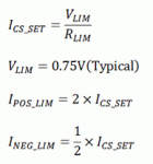
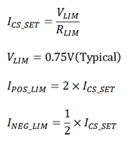
The LM5036 ensures stable CBC operation by matching the ton times of the primary MOSFET. The peak current limit threshold is adjusted through VIN to ensure reduced output current limit variation with input voltage. All of these functions are set by the three CS pins and associated external resistors. The values of these resistors can be calculated using the LM5036 Design Calculation Table. Both positive and negative currents (causing output voltage drops or even damage) will be sensed and limited.

The LM5036 device develops a new technology – input voltage compensation. By adding an additional signal as a function of input voltage on top of the current sense signal and the slope compensation signal, the change in the current limit value can be minimized over the entire input voltage range, resulting in a more precise output power limit, maximizing Threshold to avoid output power changing with input voltage. In the LM5036 device, the slope compensation signal is the sawtooth current signal ISLOPE, increasing from 0 to 50µA (typ) at the oscillator frequency (twice the switching frequency).
The compensated current sense signal can now be derived as:


The left side of the above figure is the external circuit of the LM5036 cycle-by-cycle current limit, and the schematic circuit implemented inside the LM5036. The figure on the right shows the composition of the current sensing signal. It can be seen that the LM5036 not only detects the forward current in current detection, but also increases the current value of the current sensing through the external RLIM resistor and the internal current source VLIM, thereby leaving a measurement space for sensing the reverse current and setting the reverse current threshold. At the same time, since the input voltage VIN signal is introduced into the current sensing, the sensing current contains the input voltage information. Thus, the current threshold is kept within a small range over the entire voltage input range.
At the same time, the LM5036 has a pulse matching mechanism that maintains the flux balance of the main transformer during Cycle-By-Cycle operation. The duty cycles of the upper and lower main MOSFETs are always matched to ensure that the volt-second product of the transformer is balanced, effectively preventing transformer saturation.
The pulse matching method is shown in the figure below. When the current limit is reached in phase 1, the FLAG signal inside the LM5036 goes from low to high. The RAMP signal is sampled on the rising edge of the FLAG signal, and then remains sampled and operates normally during the next half of the switching cycle of the high-side mosfet phase. When the high-side phase RAMP signal rises above the sampled value, the high-side PWM pulses are turned off, which will eventually match the duty cycles of the two phases.
Pulse matching mechanism
At the same time, the LM5306 can enter hiccup mode during overcurrent protection. Its period can be configured by an external capacitor on the RES pin. In addition to the traditional overcurrent hiccup mode, the LM5036 also supports reverse current hiccup mode protection. The LM5036 can also enter hiccup mode when backflow current occurs repeatedly. A 15µA current source is set at the hiccup restart capacitor.
(Source: China Power Grid)
The Links: LTA084A380F GD200HFL120C8SNH


