
Dry goods | Senior engineers summarize 10 kinds of complex circuit analysis methods
“The prerequisites for the calculation of circuit problems are the correct identification of the circuit and the connection between the various parts. For more complex circuits, the original circuit should be simplified into an equivalent circuit for analysis and calculation.
“
The prerequisites for the calculation of circuit problems are the correct identification of the circuit and the connection between the various parts. For more complex circuits, the original circuit should be simplified into an equivalent circuit for analysis and calculation.
There are many methods for identifying circuits, and ten methods are now introduced with specific examples.
feature recognition
The characteristics of the series-parallel circuit are: the current in the series circuit does not branch, and the potential of each point decreases successively. Identifying the circuit according to the characteristics of the series-parallel circuit is one of the most basic methods to simplify the circuit.
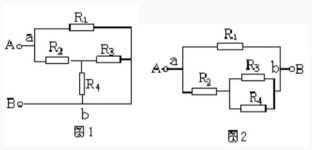
Example: Try to draw the equivalent circuit shown in Figure 1.
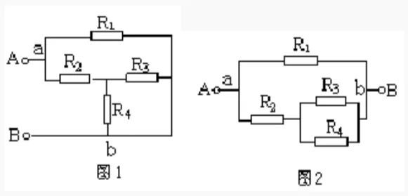
Solution: Suppose the current flows in from the A terminal, bifurcates at the a point, converges at the b point, and flows out from the B terminal. The potential of each point of the branches a-R1-b and a-R2-R3(R4)-b decreases successively, and the voltages between points a and b of the two branches are equal, so it is known that R3 and R4 are connected in parallel with R2, and then In parallel with R1, the equivalent circuit is shown in Figure 2.
Telescopic flip method
This is often done when connecting circuits in the laboratory. The unimpeded wire can be extended or shortened, or it can be turned over or turned over, and the two ends of the branch will remain stationary when turned over; the wire can also be Slide along other wires on the node where it is located, but not over components. This provides a method of simplifying the circuit, which we call the telescopic flip method.
Example: Draw the equivalent circuit of Figure 3.
Solution: First shorten the wires connecting nodes a and c, and turn the wires connecting nodes b and d to the outside of the R3-C-R4 branch, as shown in Figure 4.
Then shrink the wires connecting nodes a and c to a point, shrink the wires connecting nodes b and d to a point, and connect R5 to the wire extension line of node d (Figure 5). It can be seen from this that R2, R3 and R4 are connected in parallel, and then connected in series with R1 and R5, and are connected to the power supply.
current direction method
Current is at the heart of an analytical circuit. Starting from the positive pole of the power supply (the passive circuit can assume that the current flows from one end to the other and flows out), follow the direction of the current, and travel around the external circuit through each resistor to the negative pole of the power supply. In series, all the resistors through which the current has a bifurcation and respectively flow are connected in parallel.
Example: Try to draw the equivalent circuit shown in Figure 6.
Solution: The current flows from the positive pole of the power supply to point A and divides it into three paths (the AB wire can be shortened to one point). The first route goes directly to point D via R1, the second route goes to point C via R2, and the third route goes to point C via R3. Obviously, R2 and R3 are connected in parallel between AC points. The second and third currents converge at point c and reach point D through R4. It can be seen that R2 and R3 are connected in parallel with R4 and then connected in parallel with R1, as shown in Figure 7.
Equipotential method
In more complex circuits, points with equal potential can often be found, and all points with equal potential can be reduced to one point, or drawn on a line segment. When there is a non-power supply element between the two equipotential points, it can be removed and ignored; when a branch has neither power supply nor current, this branch can be cancelled. We call this simple circuit method the equipotential method.
Example: As shown in Figure 8, given that R1 = R2 = R3 = R4 = 2Ω, find the total resistance between points A and B.
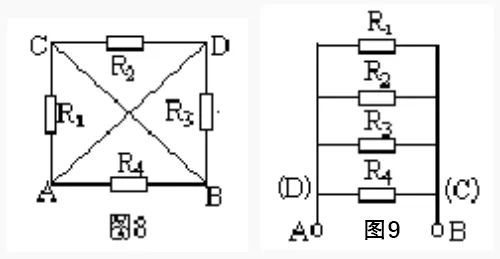
Solution: Suppose that points A and B are connected to the positive and negative poles of the power supply for analysis. The potentials of points A and D are equal, and the potentials of points B and C are also equal. Draw two line segments respectively. Resistor R1 is connected to points A and C, that is, points A and B; R2 is connected to points C and D, that is, points B and A; R3 is connected to points D and B, that is Connected to points A and B, and R4 is also connected to points A and B. It can be seen that the four resistors are connected in parallel between points A and B (Figure 9). So, PAB=3Ω.
branch node method
A node is the meeting point of several branches in a circuit. The so-called branch node method is to number each node (convention: the positive pole of the power supply is the first node, from the positive pole of the power supply to the negative pole, the nodes that pass through in sequence are 1, 2, 3…), and the branch starting from the first node. Road, draw to the negative pole of the power supply. There may be multiple branches (provided that different branches cannot pass through the same resistance repeatedly) to reach the negative pole of the power supply. The principle of drawing is to draw the branch with a small number of nodes first, and then draw the branch with a large number of nodes. Then according to this principle, draw the branch starting from the second node. By analogy for the remaining times, and finally the remaining resistors are drawn according to the positions of their two ends.
Example: Draw the equivalent circuit shown in Figure 10.
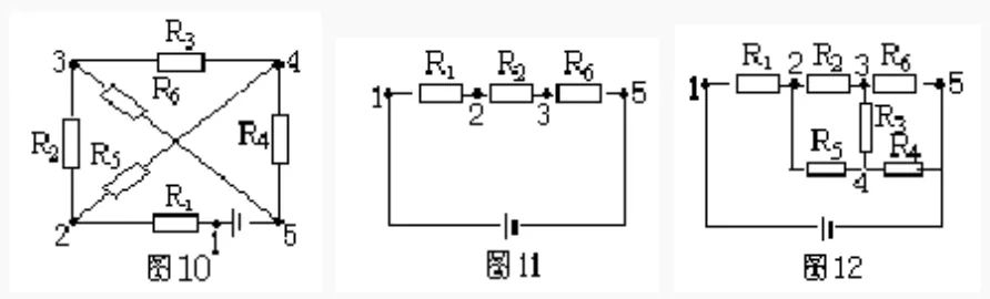
Solution: There are five nodes 1, 2, 3, 4, and 5 in Figure 10. According to the principle of branch node method, from the positive pole of the power supply (the first node), there are two branches with a small number of nodes: R1, R2, R5 branch and R1, R5, R4 branch. Take one of the R1, R2, R5 branches, and draw it as shown in Figure 11.
Starting from the second node, there are two branches that can reach the negative pole, one is R5, R4, the number of nodes is 3, the other is R5, R3, R5, the number of nodes is 4, and it is not advisable to repeat the existing R6. Therefore, the R5 and R4 branches should be drawn again, and finally the remaining resistor R3 should be drawn, as shown in Figure 12.
geometric deformation
The geometric deformation method is to carry out geometric deformation of a given circuit according to the characteristics that the wires in the circuit can be arbitrarily elongated, shortened, rotated or translated, to further determine the connection relationship of circuit components, and draw an equivalent circuit diagram.
Example: Draw the equivalent circuit of Figure 13.
Solution: Shorten the wires of the ac branch and perform geometric deformation of the circuit to obtain Figure 14, and then shorten ac to a point, and bd to a point, it is obvious that R1, R2 and R5 are connected in parallel, and then connected in series with R4 (Figure 15).
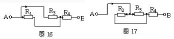
Remove resistance method
According to the characteristics of series-parallel circuits, in a series circuit, if any resistor is removed, and no current flows through the other resistors, then these resistors are connected in series; in a parallel circuit, if any resistor is removed, other resistors still have current flowing through them, then these resistors are connected in series. are connected in parallel.
Example: still take Figure 13 as an example, assume that the current flows in from the A terminal and flows out from the B terminal, first remove R2, and it can be seen from Figure 16 that there is current flowing through R1 and R3. Then remove the resistor R1, it can be seen from Figure 17 that there is still current flowing through R2 and R3. Similarly, when the resistor R3 is removed, R1, R2 also have current passing through the characteristics of the parallel circuit. It can be known that R1, R2 and R3 are connected in parallel, and then connected in series with R4.
Independent branch method
Let the current flow out from the positive pole of the power supply. On the principle of not repeatedly passing through the same element, if you see how many of them flow back to the negative pole of the power supply, there are several independent branches. The remaining resistors not included in the independent branch are added according to the positions of both ends. When using this method, select the independent branch to include the wire.
Example: Draw the equivalent circuit of Figure 18.
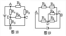
Option 1: Select A-R2-R3-C-B as an independent branch, A-R1-R5-B as another independent branch, and the remaining resistor R4 is connected between D and C, as shown in Figure 19.
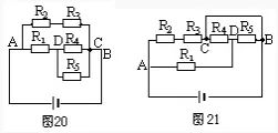
Option 2: Select A-R1-D-R4-C-B as an independent branch, and then arrange the positions of R2, R3 and R5, respectively, to form the equivalent circuit diagram 20.
Option 3: Select A-R2-R3-C-R4-D-R5-B as an independent branch, then connect R1 to AD, and connect the wire between C and B, as shown in Figure 21, the result It is still impossible to intuitively judge the series-parallel relationship of the resistors, so the unimpeded wires must be included when selecting an independent branch.
node jumper
Mark each node number in the known circuit with 1, 2, 3… numbers in order of potential from high to low (the node connected to the positive pole of the power supply has the highest potential, and the node connected to the negative pole of the power supply has the lowest potential, equal potential The nodes use the same number and merge into one point). Then the nodes are rearranged according to the potential level, and then the components are connected between the corresponding two nodes to draw the equivalent circuit.
Example: Draw the equivalent circuit shown in Figure 22.
Solution: The node numbers are as shown in Figure 22. Node arrangement, 1 and 23 nodes are arranged on a straight line at intervals, as shown in Figure 23. Return the components. Refer to Figure 22, and connect R1, R2, R3, and R4 to the equivalent circuits of 1 and 2, respectively, as shown in Figure 24.
Electric meter extraction method
If the complex circuit is connected with an electric meter, when the influence of the internal resistance of the ammeter A and the voltmeter V is not considered, since the internal resistance of the ammeter is zero, it can be removed and replaced with an unimpeded wire; because the internal resistance of the voltmeter is extremely large, it can be removed considered an open circuit. Use the above method to draw the equivalent electricity to find out the connection relationship, and then add the electricity meter to the corresponding position of the circuit.
Example: In the circuit shown in Figure 25, the influence of the internal resistance of the electric meter is negligible. Try to draw its equivalent circuit.
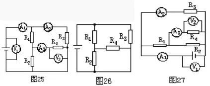
Solution: First remove the current, replace it with a wire, and then remove the voltmeter as an open circuit, as shown in Figure 26. Then connect the ammeter and voltmeter to the corresponding positions in the circuit according to Figure 25, as shown in Figure 27.
The Links: 6MBI225U-120A-05 MG100Q2YS51


