
“The upper control unit of stepping motor or digital servo motor based on various buses of PC has various bus forms, and high-speed bus can adopt bus technologies such as ISA, PCI, and USB. Usually used is based on ISA bus, PCI bus. Due to the replacement of computer motherboards, ISA slots use less and less PCI bus motion control cards and become the current mainstream. However, the PCI bus has some defects: it is easily affected by the environment in the chassis, and it is impossible to connect many devices due to the limitation of the address of the number of computer slots and interrupt resources. The USB bus has the advantages of convenient installation, high bandwidth, and easy expansion. Among them, the USB2.0 standard
“
1 Introduction
The upper control unit of stepping motor or digital servo motor based on various buses of PC has various bus forms, and high-speed bus can adopt bus technologies such as ISA, PCI, and USB. Usually used is based on ISA bus, PCI bus. Due to the replacement of computer motherboards, ISA slots use less and less PCI bus motion control cards and become the current mainstream. However, the PCI bus has some defects: it is easily affected by the environment in the chassis, and it is impossible to connect many devices due to the limitation of the address of the number of computer slots and interrupt resources. The USB bus has the advantages of convenient installation, high bandwidth, and easy expansion. Among them, the USB2.0 standard has a transfer rate of up to 480MB/s, and has gradually become the mainstream of computer interfaces. Moreover, the universal serial bus USB provides great convenience for multi-point data acquisition, and the use of USB can achieve more effective, more economical, and more points of data acquisition than traditional methods. The USB data bus has been popularized on various computers and has become the standard equipment of the computer.
2. System Architecture
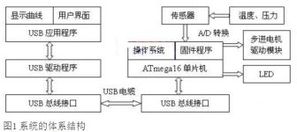
The motion control platform and acquisition card system based on USB bus mainly include three aspects: USB interface design, communication between PC and microcontroller through USB interface; motor drive, using motor driver chip UC3717A; data acquisition problems , The purpose of data acquisition is to monitor the external situation, the working environment of the stepper motor such as temperature, and capture the motion trajectory, etc. It uses the sensor to monitor the outside world through the sensing component, and converts the collected information to the single-chip microcomputer after analog-to-digital conversion. Sent by the single-chip microcomputer to the microcomputer for analysis and Display. The architecture of the system is shown in Figure 1.
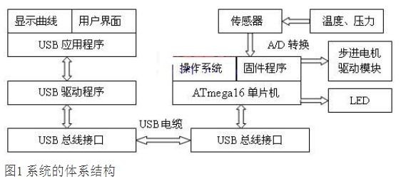
The working process of the system is a process of data acquisition and control of stepper motor operation, and each step requires the support of different groups. First, the temperature and pressure parameters are converted into analog signals by the sensor, and the analog signals are converted into digital signals that can be recognized by the single-chip microcomputer through A/D conversion; then the single-chip microcomputer processes the digital signals, and then can be sent to the LED display or sent to the USB interface chip; Then the USB interface chip sends the received data to the host through the USB for processing and display when the host needs it; finally, the processing result is used to control the operation of the stepping motor through the USB bus and the single-chip microcomputer.
3. The hardware circuit design of the system
The hardware circuit structure of the USB data acquisition system mainly includes the following parts: USB communication circuit part, data acquisition circuit part, and stepping motor drive. The functions of the modules are implemented on the hardware platform with ATmega16 as the core.
3.1 Design of USB Communication Circuit
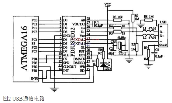
The function of the USB communication circuit is to realize the communication between the device end and the host end of the data acquisition system. This function is mainly realized by the core microcontroller ATmega16 and the USB control device PDIUSBD12. Among them, PDIUSBD12 is a chip that conforms to the USB1.1 protocol, and plays the role of a bridge connecting the device and the host in the USB communication circuit. The microcontroller ATmegal6 and the USB controller PDIUSBD12 communicate through an 8-bit parallel bus. The 8-bit parallel bus needs to connect 8 I/O ports on the ATmegal6 end. PDIUSBD12 integrates the clock multiplication PLL on-chip, and the crystal oscillator circuit uses a 6MHZ crystal oscillator and two capacitors from 2pF to 68pF. A 18-ohm matching resistor should be connected in series to the signal output terminals D+/D- of PDIUSBD12. The communication circuit is shown in Figure 2.
3.2 Design of Data Acquisition Circuit
The function of the data acquisition circuit is to convert the data such as temperature, pressure and stress on site into suitable analog signals, and then transmit the analog signals to the A/D conversion circuit. This module includes two parts: temperature acquisition module and pressure acquisition module.
The temperature data acquisition uses DS18B20, which is a digital temperature sensor produced by Dallas Company in the United States. It is the first temperature sensor in the world that supports the “one-line bus” interface, and uses the patented ON-B0ARD technology in it. All sensing elements and conversion circuits are integrated in an integrated circuit shaped like a triode. The measurement temperature range is -55°C to +125°C. The field temperature is directly transmitted in the digital mode of “one-line bus”, which greatly improves the anti-interference of the system. The new generation DS18B20 is smaller, more economical and more flexible. The collected temperature is sent to the sample and hold circuit inside the ATmegal6, and then amplified, A/D converted, and converted by the firmware program to obtain the measured temperature.
In this system, the device used to measure the pressure is a pressure transmitter produced by Guangzhou Senashi Instrument Co., Ltd., its range is 0.0lMPa, and the output signal is a current of 4~20mA.When the pressure changes, the output current also changes, so
Connect a precision resistor to the signal output, then sample and convert the voltage across the resistor, and then convert it through the firmware program to get the measured pressure.
3.3 Stepper Motor Drive Circuit Design
A stepper motor is an actuator that converts electrical pulses into angular displacement. When the stepper driver receives a pulse signal, it drives the stepper motor to rotate a fixed angle (called “step angle”) in the set direction, and its rotation runs step by step at a fixed angle. The angular displacement of the stepping motor is strictly proportional to the number of input pulses, and is synchronized with the input pulse in time. The angular displacement can be controlled by controlling the number of pulses, so as to achieve the purpose of accurate positioning; at the same time, the pulse frequency can be controlled by To control the speed and acceleration of the motor rotation, so as to achieve the purpose of speed regulation.
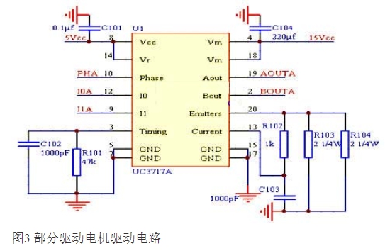
The motor drive circuit is mainly composed of drive chips, and the motor drive chip used in this system is UC3717A. The UC3717A chip is very simple to use. It receives the input parameters through 3 input pins (Phase, I1 and I0), which are connected to the MCU pins, respectively, and outputs the corresponding output by connecting to the motor on the 2 output pins (Aout and Bout). control signal. Since the UC3717A contains an H bridge, the motor drive circuit has two UC3717A counterparts connected to form a complete drive circuit. Such as 3 micro-part drive motor drive circuit diagram.
3.4 LED display circuit design
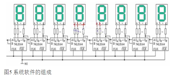
As shown in Figure 4, the display of this system is the static display used, and the characteristics of serial input and parallel output of 74LS164 are applied, and the display code is sent to the 74LS164 through the serial port of the microcontroller to be latched to achieve stable static display. A 1K resistor is connected in series between the 74LS164 and the digital tube to limit the current and play a protective role.
4. System software design
The USB data acquisition system is a multi-task system, and the program structure is relatively complex. In order to improve the development rate, enhance the stability of the system, and reduce the development and maintenance costs, an embedded operating system is needed as a platform for system development and operation. As a free embedded real-time operating system with open source code, μC/OS-Ⅱ has good stability and high reliability, and μC/OS-Ⅱ also has the characteristics of good portability, solidification and tailoring, which is very suitable as a The development platform of USB data acquisition system.
The software of USB data acquisition system consists of three parts: USB device firmware program, USB device driver program on the host PC and client application program on the host computer. The composition of the system software and the relationship between each part are shown in Figure 5.

The device firmware program can be divided into USB communication program, A/D conversion program and LED display program on the single-chip microcomputer, and the single-chip microcomputer control program for the stepper motor driver chip. The USB communication program is the main part of the entire firmware program, and its function Is to achieve USB device enumeration and data transfer. USB device enumeration is a process in which the host and the device exchange information and automatically configure after the USB device is plugged in. After the enumeration is successful, the USB interface and the host can communicate.
The device driver is the link between the device and the host application. It provides the application’s access interface (API) upward, and realizes the access and management functions of the specific device downward. Drivers are closely related to device hardware and upper-level user programs, and play an intermediary role in information conversion and transmission in the middle of the USB system. When developing USB devices, the design of device drivers is a very important link, which directly affects the performance of the entire device system.This system uses Driverworks to develop WDM type USB device driver
The main function of the application is to find the device in the device driver, exchange data with the device, and process and display the data sent by the device. The communication between the application program and the driver program is realized by accessing the application program interface (API) function, so the development of the application program must be carried out on a platform that can access the API function. Visual Studio .NET provided by Microsoft is a powerful programming tool that supports API functions. The host application program designed in this design is developed on the platform of .NET. Its functions mainly include finding USB devices and exchanging data with USB devices. And dynamic display data curve.
5. Summary
The innovation of this paper is to change the traditional use of microcomputer PCI, ISA, serial and parallel ports as communication ports, and use high-speed USB ports as communication ports. Expansion provides room for expansion; secondly, integrating the data acquisition function into the control card is also a feature of this paper: in the process of motor movement, in order to monitor the working environment of the driver, it is necessary to collect temperature data; As the basis for interpolation and adjustment, and combining the motion command output of the motor and the timely return of the motor trajectory status, a module integrating the control platform and data acquisition is formed. The process of data acquisition is a real-time process, which is a process of In the end, the system is an open real-time system. Since the implementation of the project for half a year, it has created economic benefits of more than 600,000 yuan.
The Links: G141I1-L01 PD104VT2T1


