In the design of automotive electronics, how to correctly select the power supply of the watchdog?
“With the increasing requirements for functional safety levels in automotive electronics, more and more automotive Electronic systems also use the watchdog function to improve the safety and reliability of the power supply to meet the requirements of functional safety. This article will introduce the classification, system block diagram, operation principle and typical application of the power supply with watchdog.
“
With the increasing requirements for functional safety levels in automotive electronics, more and more automotive electronic systems also use the watchdog function to improve the safety and reliability of the power supply to meet the requirements of functional safety. This article will introduce the classification, system block diagram, operation principle and typical application of the power supply with watchdog.
Generally, we divide power supplies with watchdogs into three categories:
■ Basic watchdog power supply
■ Window watchdog power supply
■ Question-and-answer watchdog power supply
1. Basic watchdog power supply
1.1 System block diagram
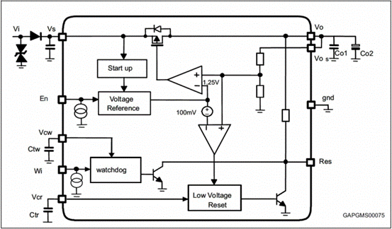
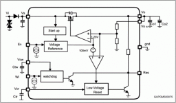
Figure 1: System block diagram of the linear regulator L4995.
Taking ST’s linear regulator L4995 as an example, it can be seen from its system block diagram (Figure 1) that the basic watchdog circuit basically has the following three functional pins:
■ Basic function pins
C Vin (battery input)
C Vo (regulator voltage output)
C GND
■ Use 3 pins to realize the function of watchdog (Wi, Vcw, Res)
C Wi (WD PWM input)
C Vcw (WD capacitor pin)
C Res (Reset)
■ Protection functions (not all protection functions are listed)
C Load current limit
C temperature shutdown
1.2 How it works
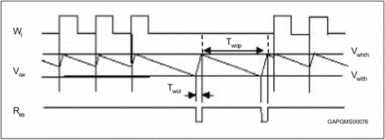
Figure 2: How the L4995 works.
The connected microcontroller is monitored by the watchdog input Wi. If a pulse is lost, the reset output pin is set low (Figure 2). With the external capacitor Ctw, the pulse train time can be set within a wide range. The watchdog circuit discharges the capacitor Ctw with the constant current Icwd. If the lower threshold Vwlth is reached, the watchdog is reset.
Each Wi positive edge switches the current source from discharging to charging. The same happens when a lower threshold is reached. When the voltage reaches the upper limit, the current switches from charging to discharging, and the result is a sawtooth wave. Vcw is the voltage at the watchdog timer capacitor Ctw.
2. Window watchdog
2.1 System block diagram
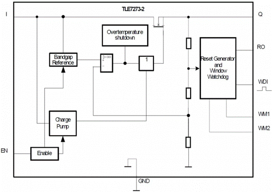
Figure 3: Low dropout regulator TLE7273-2 system block diagram.
The built-in watchdog in Infineon’s low-dropout regulator TLE7273-2 is a window watchdog, and its system block diagram is shown in Figure 3.
2.2 How it works

Figure 4: Window duration of the TPS7A63xx-Q1 built-in watchdog.
Taking TI’s low dropout voltage regulator TPS7A63xx-Q1 as an example, as shown in Figure 4, each watchdog window consists of an open window and a closed window, and the width of each window is about 50% of the watchdog window. %. There is one exception: the first window opened after the watchdog is initialized is 8 times the duration of the watchdog window. All open windows are half the width of the watchdog window except those opened after the watchdog is initialized. When initialized, the watchdog can only receive services (via software, external microcontroller, etc.) in an open window. A watchdog that is maintained in a closed window, or a watchdog that is not maintained in an open window, will cause the watchdog to report an error.
3. Question-and-answer watchdog
3.1 System block diagram
A system block diagram (Figure 5) of Texas Instruments’ TPS65381, a multi-rail power supply for microprocessors in safety-critical applications, illustrates the structure with a question-and-answer watchdog.
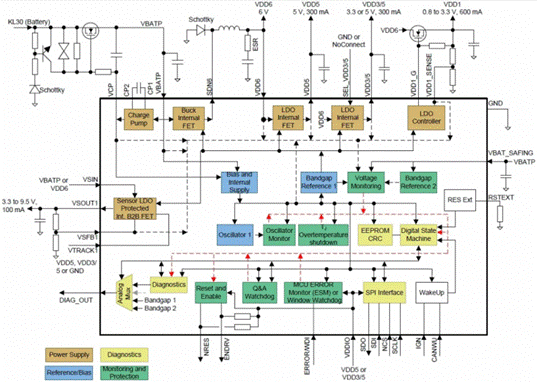
Figure 5: TPS65381 system block diagram.
3.2 How it works
Let’s use the question-and-answer watchdog of the DRV3205-Q1, TI’s three-phase motor pre-driver IC with 3 current sense amplifiers for automotive safety applications (Figure 6).
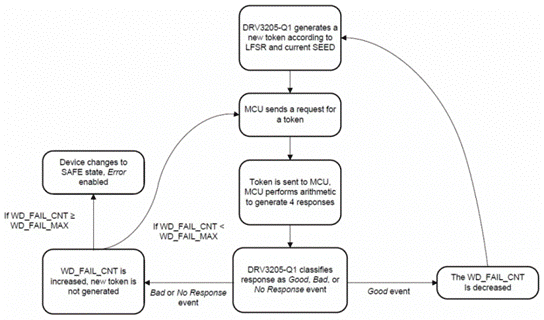
Figure 6: Simplified flowchart of the watchdog timer.
The question-and-answer watchdog operates periodically by sending a specific sequence of messages over the SPI. According to the request of the microcontroller, DRV3205-Q1 locks in the WDT_ANSWER token U value register to the MCU on the SPI. The microcontroller performs a series of fixed arithmetic operations on the token value and returns the generated token value to the SPI of the MCU by writing to the WDT_ANSWER reply register. The DRV3205-Q1 device verifies that the MCU returns the token value generated (answer) within the specified time window and the token value response (answer) is correct.
● When the MCU performs SPI communication related to the watchdog within the correct time window and returns a correctly calculated response (answer), the watchdog considers this a good event.
● When the MCU performs SPI communication related to the watchdog outside the correct timing window, or returns an incorrectly calculated token response (answer), or returns an incorrect sequence of correct answers, the watchdog considers this a bad event.
● When the MCU suspends the watchdog-related SPI communication window during the watchdog timeout period, the watchdog regards this as an unresponsive event.
● The internal counter stores the number of error responses in the wd_fail_cnt register, which is triggered.
● Fail if wd_fail_cnt reaches a predefined limit. After registering by specifying a limit in wd_fail_max, a buffer can be set for the number of bad events.
Question-and-answer watchdogs are currently used in automotive systems corresponding to functional safety levels ASIL-C/D, such as EPS. But the disadvantage of this circuit is that it increases the complexity of the control software, and also increases the cost of the hardware, which needs to be selected according to the specific system requirements.
To sum up, the power supply with the watchdog function in the car can be appropriately selected according to different applications. A compromise is required after comprehensive trade-offs in terms of cost, complexity, reliability and functional safety.
The Links: PM100CLA120 HDM64GS24Y-4-WRXF


