
“The heat dissipation problem of LED will be the main factor limiting its future success in the market. At present, many researches in the industry are focused on heat sinks, but there are few studies on the interlayer between the LED and the heat dissipation surface.
“
The heat dissipation problem of LED will be the main factor limiting its future success in the market. At present, many researches in the industry are focused on heat sinks, but there are few studies on the interlayer between the LED and the heat dissipation surface.
However, as long as we make some changes in design ideas and material use, we can not only significantly improve thermal management performance and reliability, but also get a more simplified system. The use of ceramics as a part of heat sink, circuit carrier and product design requires us to have some new thinking modes and willingness to overcome traditional design modes.
The simulation process based on computational fluid dynamics (CFD) supports thermal optimization and product technical design. This article will explain the theoretical basis, proof of concept, and how to achieve these improvements with ceramic heat sinks.
1 Module optimization
As we all know, LED has high luminous efficiency, and because of its small size, it is favored by designers. But only when thermal management is not considered, they are really “small”. Although compared with the incandescent light source’s working temperature of up to 2500°C, the temperature of the LED light source is much lower. Therefore, many designers finally realize that heat dissipation is a big problem. Although the LED also generates heat, it is relatively low, so heat dissipation is not a problem for the LED itself. However, the allowable operating temperature of semiconductor devices that drive LEDs is lower than 100°C.
According to the law of conservation of energy, thermal energy must be transferred to the surrounding area. The LED can only use a small temperature gap between the 100°C hot spot and the 25°C ambient temperature, so only 75 Kelvin is available. As a result, a larger surface and powerful thermal management are required.
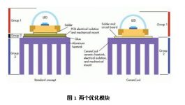
The two optimized blocks are shown in Figure 1. Group 1 is an LED, which is basically not touchable. Its center part is a bare chip and a heat-dissipating copper metal block, which is used to connect the bare chip and the bottom of the LED. From the perspective of heat dissipation, the ideal solution is to bond the die directly to the heat sink. But from the point of view of mass production, this idea is commercially unrealistic. We regard LED as a standardized “catalog” product that cannot be modified. It is a black box.
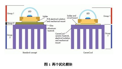
Group 2 contains a radiator, which transfers the energy of the heat source to the air. Normally, the surrounding air is free or forced convection. The less beautiful the heat dissipation material, the more it needs to be hidden. But the more you hide, the lower the cooling efficiency. In contrast, beautiful and high-value materials can be used. These heat dissipation materials are directly exposed to the air and become part of the visible product design.
Between Groups 1 and 2 is Groups 3, which provides mechanical connections, electrical insulation, and heat transfer. This seems to be contradictory, because most materials have good thermal and electrical conductivity at the same time. The reverse is also true. Almost every electrical insulating material is also a thermal barrier material.
A good compromise is to solder the LED on the PCB, and then glue the PCB to the metal heat sink. In this way, the initial function of the PCB can be maintained. Although PCBs have many different thermal conductivities, they are still an obstacle to heat transfer.
2 Radiator selection
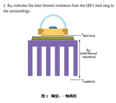
The thermal resistance of the LED (die to heat sink metal block) and heat sink can be obtained from the manufacturer, but they are a bit biased towards Group 3 and its significant impact on overall heat dissipation performance. When you add all the thermal resistances except LED (Group 1), you get the total thermal resistance (RTT) (see Figure 2). RTT allows you to make a true comparison of system cooling performance.
The usual practice is to optimize only the heat sink. At present, there are hundreds of LED heat dissipation designs, basically all of which use aluminum radiators. But if you want to further improve the heat dissipation effect, you must go further or even eliminate Group 3. Electrical isolation can be achieved by the heat sink itself through other materials. Our conclusion is ceramics. Ceramics (such as Rubalit (aluminum oxide) or Alunit (aluminum nitride)) have two key properties at the same time, namely, electrical isolation and heat conduction.
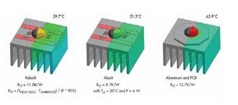
Rubalit has a lower thermal conductivity than aluminum, but Alunit has a slightly higher thermal conductivity than aluminum. On the other hand, Rubalit is cheaper than Alunit (see Figure 3). Their thermal diffusivity can meet the heat dissipation needs of semiconductor chips. In addition, they are rigid and corrosion resistant, and comply with the European Union’s Restriction of Hazardous Substances Directive (RoHS).
The simplified structure (no glue and insulating layer, etc.), coupled with the direct and YJ bonding between the high-power LED and the ceramic radiator, creates an ideal operating condition for the entire assembly work. This brings great long-term stability, safe thermal management and high reliability. We have applied for ZL for this new idea, named CeramCool.
2.1 Theoretical basis
CeramCool ceramic radiator is an effective combination with radiator, it can reliably cool heat sensitive components and circuits. It realizes the direct connection between components and YJ. In addition, the ceramic itself is electrically insulating, and it can provide a bonding surface through the use of metal sheets. If required, customer-specific conductor track structures can be provided, even three-dimensional.
For power electronics applications, direct copper bonding is possible. The ceramic heat sink can be turned into a module substrate, which can be densely mounted with LEDs and other components. It can quickly dissipate the generated heat without creating any barriers.
2.2 Verification of new ideas
The idea of using ceramics was initially cross-checked in several simulation models. In order to predict the thermal performance of different designs, a CFD-based method was invented. In addition, an optimized 4W LED ceramic heat sink has been developed. Manufacturing requirements were taken into consideration during development.
The optimized geometric layout allows the 4W LED to work below 60°C and has passed the physical test. The design is a square layout (38? 38? 24 mm) and contains longer and thinner fins that take up more space. The same geometric layout on the aluminum substrate can withstand higher temperatures. Depending on the thermal conductivity of the PCB (from 4W/mK to 1.5W/mK), the temperature will rise to between 6 and 28K.
At present, the 6K reduction in hot spots means that the pressure on LEDs has been greatly reduced. The total thermal resistance of Rubalit assembly is at least 13% better than that of aluminum, under the same layout. When using Alunit, the Z-low improvement of CeramCool will reach 31%. If there is a thermal drop of 28K, then these solid results are largely due to the extreme performance of the above two ceramics.
3 Solution
In the second part of this article, we discussed how to calculate the thermal resistance of LEDs and heat sinks, and how to use ceramics for one thing. In the third part of this article, we will discuss the flexibility of the idea, the simulation model of customized solutions, the transformation and isolation of existing lamps, and the sub-assembly methods to improve the design of existing LED systems.
This idea is flexible and can be used for different goals. You can choose to run the LED at a Z-optimal temperature to ensure long life and high lumens per watt. You can also choose to run the LED at a higher temperature, but accept a shorter LED life and efficiency. A temperature distribution from 50°C to 110°C is common. If you need more lumens, 5 or 6W LED design can be equipped with 4W heat sink. Decomposing such high power into several 1W power LEDs helps to improve heat dissipation: 65°C at 5W and 70°C at 6W (see Figure 4).
With the chip YJ and reliable bonding to the electrical insulation CeramCool, the ceramic heat sink carries more heat and becomes hotter. It can eliminate the heat dissipation burden of the LED and effectively cool this key component. The reduced die temperature also allows the use of a smaller surface, so the ceramic heat sink can be made smaller.
3.1 Simulation model of customized solution
Since most applications using CeramCool are customized solutions, it is necessary to verify its performance before DY expensive prototypes are released. To this end, a lot of research has been done to establish a simulation model. These simulation models have been verified by various tests and have proven their reliable correlation with the test results. Based on this understanding, new ideas or changes can be easily evaluated.
3.2 Lamp modification and isolation
The problem of lamp modification mainly involves isolation. Any retrofit lamp must be of Class II structure, because you cannot guarantee to provide an electrical ground. This means that any exposed metal blocks must be isolated from the AC power traces by double or reinforced insulation.
Modifications of metal radiators often fail to comply with this point, because they require a greater distance (such as 6 mm in the air) or double insulation, which will affect the normal operation of the radiator. The Electronic driver integrated in the GU10 LED is so limited in space that the product becomes very complicated. With the help of ceramic radiator, even if the driver is not working at all, the radiator will not conduct AC current, so the product is still safe.
CeramCool GU10 LED spotlight can work with any LED. The socket and reflector are made of the same high-performance ceramic material. Therefore, it has a simple Class II structure with safe insulation. The Z high temperature of a high-voltage 4W LED can only reach 60°C, which not only improves the service life of the LED but also enhances the light output.
In all CeramCool radiators, the substrate becomes a radiator. Here, it acts as a lamp or even a luminaire. This simplified design provides extremely high reliability. In addition, the installation and reflector of the GU10 LED spotlight are usually made of different materials. This solution uses far fewer materials and ceramics have been developed for electrical insulation, good EMC and high mechanical/chemical stability.
The Links: CM600YE2N-12F SKIIP24NAB125T12


