

How to use power modules and wide bandgap to achieve dual battery management in mild hybrid vehicles
“In order to cope with climate change and reduce travel pressure, the state has issued a series of policies, including the implementation of the “National VI” emission standards. The outside world refers to the “National VI” emissions as the most stringent “emission standards” in history. In fact, since the implementation of the “National VI” standard, many car owners have stated that exhaust emissions have been reduced by half, but vehicle power has also been significantly reduced compared to before, and even fuel consumption has increased. It is imperative to reduce automobile emissions and fuel consumption. To achieve this goal, one of the ways is to use hybrid power, that is, add an electric motor driven by a second battery to the transmission chain of a gasoline or diesel vehicle.
“
In order to cope with climate change and reduce travel pressure, the state has issued a series of policies, including the implementation of the “National VI” emission standards. The outside world refers to the “National VI” emissions as the most stringent “emission standards” in history. In fact, since the implementation of the “National VI” standard, many car owners have stated that exhaust emissions have been reduced by half, but vehicle power has also been significantly reduced compared to before, and even fuel consumption has increased. It is imperative to reduce automobile emissions and fuel consumption. To achieve this goal, one of the ways is to use hybrid power, that is, add an electric motor driven by a second battery to the transmission chain of a gasoline or diesel vehicle.


Traditional Electronic technology uses a high-voltage battery, usually with a voltage between 300 and 400 V, coupled to a high-performance electric motor. These “full-hybrid” cars can significantly improve fuel efficiency, but also greatly increase cost and body weight. And “plug-in” hybrid vehicles, in which the battery is charged through an AC power socket, have similar disadvantages.
An alternative is the “Mild Hybrid Electric Vehicle” (MHEV), which uses a small 48 V battery to drive the electric motor, which can achieve faster acceleration and greater low-end torque, while still improving fuel economy, and only Will moderately increase cost and complexity. The advantages of mild hybrid systems are favored by consumers. According to analysts from IHS Markit, 48 V mild hybrid vehicles will account for nearly 50% of hybrid vehicle sales by 2025. The cost of the 48 V system is lower, so it is also very attractive to car manufacturers.
The addition of a 48 V lithium-ion battery means that the MHEV is a dual-voltage vehicle, which also creates its unique design challenges, mainly in how to manage the battery charge and discharge cycle while maintaining system efficiency. In this article, we will discuss these challenges and explore the benefits of using automotive power modules and new wide bandgap transistors based on wide bandgap technology for power converters.
48 V architecture
The most basic hybrid system (see the picture below) includes a battery, an integrated starter generator (ISG), a 48 V to 12 V converter, and one or more 48 V loads, just like a stable system. Since the 48 V mild hybrid system retains a 12 V battery and multiple 12 V loads, these systems will continue to use a dual voltage architecture for the foreseeable future.
48 V mild hybrid system
ISG is responsible for vehicle power supply, vehicle startup and energy recovery during braking.
Except for the absence of a 12 V alternator, the 12 V battery part of the system remains the same. Since there is no 12 V power generator in the ICE, a bidirectional converter is needed to realize the power conversion between the 48 V system and the 12 V system.
MHEV bidirectional converter working mode
The bidirectional converter has a variety of operating modes. During the start of the vehicle, the ISG is powered by a 48 V lithium-ion battery. If the 48 V battery is insufficient or cannot provide enough power (for example, due to low temperature), the converter will work in boost mode, using the 12 V battery to provide additional starting current. Normally, the engine start/stop function will be disabled until all systems reach the normal operating temperature, at which point the vehicle will start to restart normally.
When the vehicle reaches normal temperature and is driving, but no additional acceleration is required, the converter will work in step-down mode to charge the 12 V battery with a 48 V battery and supply power to the 12 V load. When additional power is needed, the converter will switch to boost mode again to provide supplementary power for the ICE, reducing fuel consumption and overall emissions.
Converter topology
48 V to 12 V converters usually have a wide power range of (1~3) kW. In order to maintain high energy efficiency in this range, multi-stage interleaved buck-boost converters are the most popular choice.
The buck topology provides a voltage drop, in this case a voltage drop of 48 V to 12 V, while the boost topology provides the opposite power conversion. The synchronous topological structure keeps the power switch fully open for most of the time in the two modes, thereby improving the overall efficiency of the converter.
The multi-phase interleaved design connects several identical converter phases in parallel (for a single-phase example, see “Bidirectional Converter-Single Phase” in the picture below) to act as a single high-power converter. In the case of heavy load, all phases work, but during light load, the battery disconnect switch can be used to turn off some loads, thereby reducing losses and improving efficiency. Each phase will produce an output current with a slightly different phase angle, thereby reducing the ripple of the output capacitor. Using an interleaved converter instead of a single large converter means that the current in each phase is smaller, thereby reducing the stress on the power switch, conductors, and inductors (see the picture below “Multi-phase buck-boost in configuration converter”).
Bidirectional converter-single phase
Multiphase buck-boost converter in an interleaved configuration
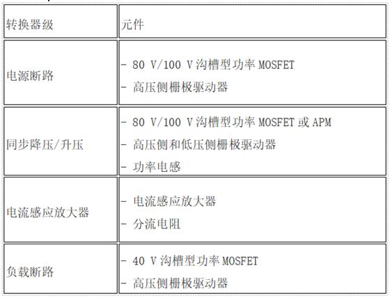
The main modules in this type of converter include power disconnect switch, buck-boost half bridge, current sensing stage, main Inductor and load disconnect switch.
The synchronous buck-boost converter actually combines two switching circuits into a single-stage circuit. The power switch controls the current flow in the main energy conversion element (inductor). The inductor current is the main variable that needs to be controlled because it is essential to ensure excellent system accuracy.
The direction of the inductor current determines the direction of the power supply current, which determines the battery that receives the current. The system controller determines the current direction by generating the appropriate switching pattern (see picture below).
Basic buck-boost conversion
Converter design
The main circuit components required are summarized in Table 1. Both power disconnection stage and load disconnection stage can use discrete MOSFET or integrated MOSFET power module. The main purpose of these stages is to isolate the input and output of each interleaved stage from other stages and 48 V (source) and 12 V (load) batteries, respectively, by using a back-to-back switch configuration. Since these MOSFETs all operate at floating voltage potential, each device is controlled by a gate driver with high-side drive function. MOSFET may need to maintain conductivity for a longer period of time, so it must be able to conduct 100% in time.
Table 1 The main functional modules of the buck-boost converter applicable to the dual-voltage MHEV system
The buck-boost stage is the core of the converter and consists of two MOSFET devices in a half-bridge configuration connected to a power inductor. These MOSFETs must be controlled by high-side and low-side gate drivers that can be packaged individually or in combination into dual driver ICs. Alternatively, a small car power module (APM) (see picture below) can be used to achieve this level.

Design based on automobile power module
This integrated power module from ON semiconductor adopts a small package that meets AEC requirements and has low thermal resistance, low internal resistance and higher EMI performance. In this implementation, no power cut-off circuit is used; for individual phase isolation, a load cut-off circuit can be used.
The main power inductor stores the energy of each converter phase and will transfer it to any battery. The converter controller is responsible for controlling the two main switches that determine the direction of the current. In order for the stage to operate normally, the current must be accurately measured to properly adjust the main inductor current. It is best to use a current sense amplifier based on a shunt resistor because its error is extremely low.
By using high-precision shunt resistors, we can measure very small differential voltages, usually tens or hundreds of mV, and the shunt voltage itself can vary from 0 to 48 V to ground. This huge difference means that the amplifier must amplify smaller differential signals and provide a higher common-mode voltage rejection ratio, while being able to withstand transient voltages up to 80 V. Therefore, 3 amplifier specifications must be carefully selected:
● Common mode voltage range (the wider the better);
● Input offset voltage (the smaller the better);
● Common mode rejection ratio (the higher the better).
In traditional operational amplifiers, the input voltage is limited to the supply rail voltage of ±0.6 V, which greatly limits the common-mode voltage range. In recent years, dedicated current sense amplifiers have provided a larger common-mode voltage range, up to 80 V. They also provide high-precision offset voltages as low as 10 µV, which can support highly accurate and fast current monitoring systems.
Converter design using wide band gap
As the requirements for size and efficiency in automotive applications continue to increase, wide bandgap (WBG) devices (such as products from ON Semiconductor) have become alternatives to standard silicon devices. Wide bandgap devices can improve efficiency and reduce size, while reducing the total system cost.
Because wide bandgap devices can significantly reduce switching losses, the use of wide bandgap buck converters can achieve conversion speeds several times that of typical silicon power transistors, thereby minimizing electromagnetic interference in the frequency range that may affect AM radio reception. interference. In addition, the wide band gap transistor does not have reverse recovery loss, so there will be no large current spikes and power loss during hard switching.
Summarize
With the popularity of a large number of new mild hybrid vehicles, more and more cars are equipped with 48 V battery subsystems, which require the use of 48 V to 12 V converters. Although many different converter topologies can be used, the bidirectional interleaved synchronous buck/boost converter has become the most widely used structure due to its simplicity and efficiency.

The topology can also be designed with multiple interleaved phases, so that high efficiency can be achieved in a larger working range. This is very important because the load of a 12 V vehicle will vary greatly over time. Even if the converter needs to be able to work under the maximum load condition, it rarely stays under this load condition for a long time. When the load is light, the converter will turn off unnecessary interleaved phases to reduce losses and maintain high efficiency.
The Links: MG25Q6ES43 6MBI50J-120


