

“The emergence of the CAN bus provides a strong technical support for the distributed control system to realize real-time and reliable data communication between nodes. While bringing convenience, it also increases the difficulty for engineers to troubleshoot. Therefore, this article mainly for everyone Three ways to find CAN bus (faulty) nodes are introduced.
“
Abstract: The emergence of the CAN bus provides a strong technical support for the distributed control system to realize real-time and reliable data communication between nodes. While bringing convenience, it also increases the difficulty for engineers to troubleshoot. Therefore, this paper mainly focuses on Three ways to find CAN bus (fault) nodes are introduced to you.
1. Unplug all nodes and connect them in sequence.
When the CAN bus fails, all nodes are unplugged, and then one node is connected up, and when the system fails, the last inserted node is found to be the faulty node. In the following situation, Figure 1 shows the control bus of the new energy vehicle. After the vehicle is started, the instrument Display lags and displays an error. This leads to delays and errors in the driver’s judgment, affecting traffic safety. After unplugging all the nodes, use this method to connect the nodes one by one until the motor controller is connected to the bus and there is a communication failure. It is initially judged that the strong interference generated by the motor operation causes the crosstalk to the CAN bus, resulting in an increase in frame errors. Retransmission is frequent, and correct data cannot arrive in time.
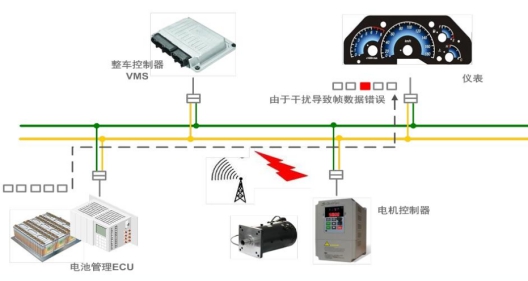
Figure 1 New energy vehicle control bus
2. According to the level characteristics, find the position of the faulty node
We followed the above case to verify by this method. Figure 2 below is the error frame waveform we tested using CANScope to connect to the OBD interface under the steering wheel.
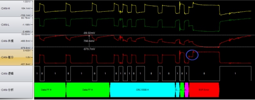
Figure 2 Waveform of error frame
As can be seen from the blue mark, after the ACK response, there is a low step first, and then a second raised error frame. This error flag is formed by the superposition of active error flag + error flag, and the secondary increase is 6 continuous dominant levels, which are caused by the superposition of error flags of each node due to global notification after a node error. That is to say, there is a certain CAN node on the vehicle network that is more susceptible to interference and local errors occur.
How to quickly analyze the error node? Use CANScope to connect to the OBD interface at the front of the car and test the motor controller at the rear of the car respectively. The results are shown in Figure 3:
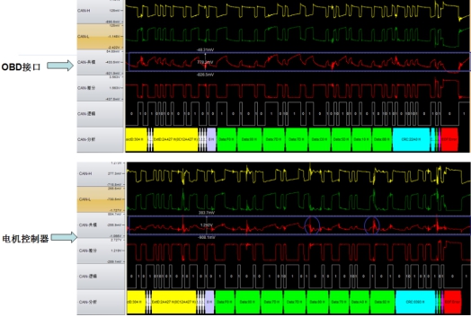
Figure 3 Common mode interference comparison
As shown in the figure above, the common mode amplitude tested at the OBD interface is more than 700 mV, and the common mode amplitude tested at the motor controller node is about 1.3V, and periodic interference pulses can be seen at the same time. By performing FFT spectrum analysis on the abnormal common-mode signal, the common-mode interference frequency can be quickly located. The test results are shown in Figure 4:
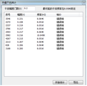
Figure 4 Interference frequency
The tested interference frequency is consistent with the frequency of the motor driver. It is inferred that the huge current generated by the inverter of the driver forms a strong interference, and the crosstalk is transmitted to the CAN bus, causing local errors in the nodes closer to it.
3. Use multi-channel CAN card to find faulty nodes
As shown in Figure 5, the USBCAN-8E-U used is connected to the CAN network through USB, and can monitor and collect data synchronously on the data of up to 8 CAN buses.
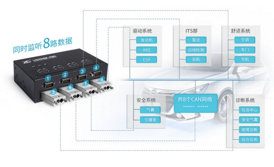
Figure 5 CAN card monitoring
And with the integrated analysis process of the host computer, the source of data errors can be traced, as shown in Figure 6, box 1 is the original message, box 2 is the error message, box 3 is the statistical information, and the bus can be deeply diagnosed and analyzed to find out the fault. node.
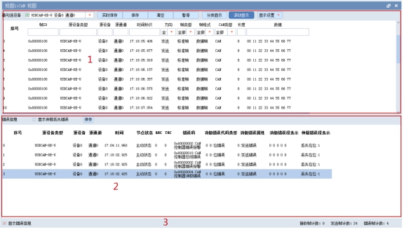
Figure 6 CAN view
The Links: NL160120BC27-10 AT24CM01-XHD-T


