
“Mobile robots use navigation technology to obtain the current position of the robot, combine with sensor technology to detect the surrounding external environment (obstacles, etc.) in real time, and plan a feasible path according to the information provided by the environment to complete the task of reaching the target point. Mobile robot technology involves many fields such as sensor technology, navigation technology, computer technology, artificial intelligence, etc. Therefore, high requirements are placed on the control part of mobile robots, especially the emergence of visual sensors, which requires the control system not only to have a large storage capacity, but also Processing speed is fast, etc.In the past, mobile robots based on PLC and single-chip control could not meet the real-time requirements very well.
“
1 Introduction
Mobile robots use navigation technology to obtain the current position of the robot, combine with sensor technology to detect the surrounding external environment (obstacles, etc.) in real time, and plan a feasible path according to the information provided by the environment to complete the task of reaching the target point. Mobile robot technology involves many fields such as sensor technology, navigation technology, computer technology, artificial intelligence, etc. Therefore, high requirements are placed on the control part of mobile robots, especially the emergence of visual sensors, which requires the control system not only to have a large storage capacity, but also Processing speed is fast, etc. In the past, mobile robots based on PLC and single-chip control could not well meet the characteristics of real-time rapidity.
With the emergence and development of ARM processors and the development of embedded systems, the real-time and rapidity requirements of mobile robots can be well satisfied. Now this technology has been effectively applied in many fields. In this paper, a low-power and high-performance 32-bit processor chip S3C44B0X based on ARM7TDMI core of SAMSUNG company is used as the control core, and the 16-bit single-chip microcomputer SPCE061A of Sunplus is used as the auxiliary processor to process the obstacle information detected by the sensor. Real-time multitasking operating system? C/OS-II manages the realization of the mobile robot’s navigation algorithm and the execution of multitasking. The experimental results show that the system can achieve obstacle avoidance and navigation functions and reach the destination smoothly.
2. Hardware design of control system
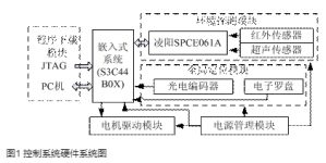
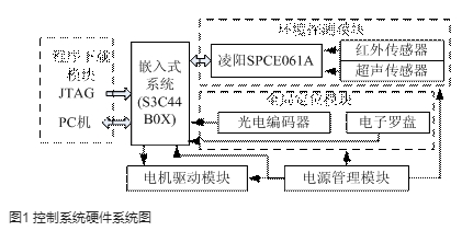
The control system of the mobile robot mainly completes functions such as detection of external obstacles and information transmission, acquisition of the current position of the robot, path planning, and operation control. The system is divided into functional modules. The system can be divided into the following five modules: environment detection module; global positioning module; program download module, motor drive module and power management module. The relationship between the various modules is shown in Figure 1.
2.1 Environment Detection Module
In the process of obstacle avoidance and path planning, the mobile robot must detect the information of the surrounding obstacles in real time and measure the distance of the obstacles. At present, there are infrared, ultrasonic, laser and visual (CDD) sensors. The laser sensor is greatly affected by the environment and is relatively expensive. The visual sensor (CCD) requires a large storage capacity of the chip and requires a fast processing speed, which is not easy to use. Based on this, this paper installs a set of infrared sensors and ultrasonic sensors on the front, left, and right of the mobile robot to measure the distance of obstacles in three directions. The use of multiple sensors can avoid the blind spot that exists in the measurement of a single sensor.
The infrared sensor is composed of a transmitter and a receiver. The 3-way transmitter ports of this sensor are connected to the 3-way I/O ports of the Lingyang MCU SPCE061A, and the 3-way receiver ports are connected to the other 3-way MCU. When the I/O output of the single-chip microcomputer is at a high level, the transmitter port emits infrared light, and the light wave encounters obstacles and is reflected by the receiver, generating a current with relative light intensity through A/D conversion and inputting the single-chip computer, and the distance of the obstacle is calculated according to the voltage. . The working principle of the ultrasonic sensor is basically the same as that of the infrared sensor. The sound wave encounters an obstacle and returns to the receiver to be accepted, and the distance of the obstacle is calculated according to the time difference.
The detection module can measure obstacles within a distance of 0 to 2m, with small measurement errors. It uses 16-bit Sunplus microcontroller SPCE061A to quickly process the obstacle information. Once an obstacle is detected, it communicates with S3C44B0X through the bus interface and transmits data.
2.2 Global positioning module
The determination of the current position of the robot is very important and provides essential information for the robot path planning. At present, positioning sensors include global positioning system (GPS), rotary potentiometer, photoelectric encoder, magnetic compass, Electronic compass, accelerometer and so on. According to the use environment, this module adopts the method of combining the photoelectric encoder and electronic compass produced by Changchun First Optical Co., Ltd. to determine the current coordinate point of the robot. After photoelectric conversion, the photoelectric encoder converts the angular displacement of the shaft into an electrical pulse signal, which is output to the counter T1 of the S3C44B0X through the amplifying circuit, and stores the pulse collected at a specific time. The pulse signal is proportional to the number of turns of the wheel. Proportional, so the actual distance of the robot can be calculated. The electronic compass adopts Honeywell’s low-cost HMR3100 plane electronic compass, with HMC1022 two-axis magnetic sensor inside, and the angle measurement accuracy can reach 5 degrees. The electronic compass can determine the absolute direction of the robot relative to the north pole, and can accurately measure the movement direction of the robot. deviation from the theoretical direction, thereby correcting the trajectory of the robot.
2.3 Program download module and motor drive module
The program download module mainly completes the download of the startup program and the application program. The system provides two download methods, serial port download and parallel port download. The serial download is connected to COM1 on the board through RS232 serial line to communicate with the PC, and the parallel download is connected to the JTAG debugging interface through the parallel line to complete the communication between the PC and the S3C44B0.
The accuracy of the motor drive module has a great influence on the accuracy of the entire system. Considering various factors, this module selects an integrated driver IR2110 based on a dual-channel, high-voltage, high-speed gate drive method. The IR2110 driver chip can convert the input logic signal into a low-impedance output driver signal of the same phase, and can drive 2 outputs on the same bridge arm. The characteristics of strong driving ability, fast response speed, high operating voltage and low cost improve the system. accuracy and reliability. The motor adopts an ordinary high-power DC geared motor and a high-power H-bridge drive circuit. The circuit principle is shown in Figure 2.
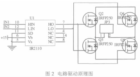
In the circuit, IR2110 is used as a pre-driver, and four IRFP250s form an H-bridge driving circuit. When a PWM signal is applied to IN1 and a low level is applied to IN2, Q2 and Q5 are turned on, Q3 and Q4 are turned off, and the motor is driven forward; when a PWM signal is applied to IN2 and a low level is applied to IN1, Q3 and Q4 are turned on. On, Q2 and Q5 are off, and the drive motor is reversed. Adjusting the PWM pulse width can adjust the motor speed. In order to make the motor run smoothly, the frequency of the PWM signal is not lower than 1KHZ.
3. System software implementation
The realization of the software part is based on the real-time multitasking operating system ported to S3C44B0X? C/OS-II, which is a priority-based, preemptive real-time kernel, with open source code, good portability, tailoring, multitasking, etc. , can manage 64 tasks, the application can reach 56 tasks. It mainly completes functions such as task management, time management, semaphore management, and memory management.
The robot mainly completes obstacle avoidance detection and information transmission, position acquisition, path planning, and operation control functions. Therefore, the system has created a total of 4 tasks, task 1: obstacle avoidance detection and information transmission, task 2: position acquisition, task 3 : Path Planning, Task 4: Motor Drive Control. The priority of the tasks decreases in turn, and information is passed between the tasks through the fuel tank. After the mobile robot completes the initialization system, it drives the motor to execute task 4 and move forward to the target point according to the predetermined path. At the same time, the sensor controlled by the single-chip SPCE061A works. When the sensor detects an obstacle around, task 1 enters the ready state. Due to the priority of task 1 If the level is high, it will seize the right to use the CPU to complete the processing and transmission of obstacle information. Through the transmission of the semaphore, task 2 enters the ready state, completes the calculation of the current position, and provides a basis for path planning. Task 3 starts the navigation algorithm for path planning according to the obstacle information provided by task 1 and the information location information provided by task 2. After the new path planning is completed, task 4 enters the running state to complete the final specified task.
4. Experimental results
The experiment was carried out indoors, with a site area of 12m × 12m, and a green blanket-like substance was attached to the surface of the site to prevent slipping. Grid-based navigation algorithm is used for path planning. The shape and size of the robot is 0.8m×0.8m×0.6m, and the grid size is 0.8m×0.8m. The total is 15×15=225 grids. Use blocks and other robots as stationary obstacles. The trajectory of the mobile robot is shown in Figure 3. The light gray box in the figure is an obstacle, and the dark gray box route is the trajectory of the robot. The starting point and target point are marked as shown in Figure 4 below. The experimental results show that the robot can avoid obstacles to reach the target point, and the position error is 0-0.4m, which is feasible.
5 Conclusion
The author’s innovation is to use the high-performance ARM chip S3C44B0X as the main control and the single-chip SPCE061A as the auxiliary controller to control the robot, and introduce the embedded real-time operating system C/OS-II to complete the realization of the robot navigation algorithm As well as reasonable planning and scheduling of multiple tasks of the robot, as well as ensuring the rapid response of the robot to the unknown environment and the accuracy of the entire system, experiments have proved the feasibility of this method.
The control system has abundant hardware resources, and the processing of the information obtained by the sensor also adopts the high-performance single chip SPCE061A, which provides the hardware basis for the use of the vision sensor (CCD) in the future. Later system upgrades provide convenience. More advanced navigation algorithms can also be used to make it more intelligent.
The Links: LQ121K1LG52 LM150X05-A3C1


