
A very classic voltage failure monitoring circuit of a large company, have you learned it?
The circuit is in an unstable state when the voltage is lost, and some countermeasures are often required. For example, the audio, the internal audio power amplifier circuit, will emit a harsh popping sound when the power is suddenly unplugged.
If a voltage power failure monitoring circuit is added, when the voltage power failure is detected, a signal is output to trigger the mute circuit to work, and the popping sound can be eliminated. (The mute circuit can be by adding a relay between the audio power amplifier circuit and the speaker. When mute is required, the control relay is disconnected from the speaker)

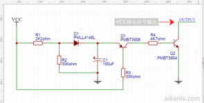
The figure above is a voltage brownout monitoring circuit to be introduced here.
Circuit Description
The voltage power-down monitoring circuit monitors the voltage VCC. When the voltage of VCC drops to a certain threshold, the transistor Q2 is turned on, and the external voltage can be pulled to 0V; otherwise, Q2 is not turned on, which is equivalent to an open circuit to the outside.
Principle analysis
VCC is the voltage to be monitored. Here we take VCC equal to 12V as an example for analysis.
1. When VCC is powered on, the capacitor C1 is charged through the resistor R1 and the diode D1. After VCC is stabilized at 12V, the left side of D1 is 11.25V after the voltage division of R1 and R2. After D1, a diode voltage drop is reduced, that is, 0.7V, and the voltage of capacitor C1 is charged to 10.55V.

2. After VCC is stabilized at 12V, the b pole of Q1 is also 12V. Since the voltage of the b pole is higher than that of the e pole, the transistor Q1 does not conduct. Q1 is not conducting, then the b pole of Q2 has no voltage, and Q2 is not conducting.

3. When VCC is powered off, it needs to drop to a certain threshold before Q2 will be turned on and output the VCC power-off signal externally. The figure below shows the three discharge circuits.
Discharge circuit ①: When VCC drops to 9.85V, the voltage of capacitor C1 is 10.55V when fully charged, which is 0.7V higher than the b pole (9.85V) of Q1, C1 discharges through the eb pole of Q1, resistor R3 and VCC, So Q1 is turned on.
Discharge circuit ②: After Q1 is opened, the voltage of capacitor C1 goes to the ground through the ec pole of Q1, the be pole of resistor R4 and Q2. The b-pole voltage of Q2 is 0.7V, so Q2 is turned on.
Discharge circuit ③: After Q2 is opened, pull the voltage of the external circuit to the ground, and tell the external circuit through this action: VCC is powered off!
Circuit parameter setting description
The response threshold of the voltage detection circuit can be set: the method is to adjust the ratio of R1 and R2. The above example is when VCC is powered down to 9.85V, the circuit outputs a power down signal.
The duration of the circuit output power-down signal can be set: the method is to adjust the capacitance value of C1 and the resistance value of resistor R3. If the value of C1, R3 and R4 is increased, the discharge time of C1 can be prolonged, which also prolongs the time that Q2 is continuously pulled low, and finally prolongs the duration of the circuit outputting the power-down signal. Know that sometimes persistence is important. . .
The Links: HSD150SX84-G AD9513BCPZ


