

Inspection method for common problems of inverter switching power supply module
“The following will explain the detection methods and repair methods of the three common problems of the inverter switching power supply module one by one. Of course, it is not necessarily 100% able to solve all problems. It is still necessary to accumulate experience and become proficient slowly. .
“
The following will explain the detection methods and repair methods of the three common problems of the inverter switching power supply module one by one. Of course, it is not necessarily 100% able to solve all problems. It is still necessary to accumulate experience and become proficient slowly. .
The switching power supply circuit of the inverter can be completely simplified into the circuit model shown in the figure below. The main key elements in the circuit are included in it. When we are familiar with any complex switching power supply, there will be a backbone like the figure below. In fact, in the maintenance, we must have the ability to “simplify” complex circuits. In the chaotic circuit expansion, we must find these main contexts and train ourselves so that there is no overall switching power supply circuit in front of us, only each part. The direction of the context and context – the oscillation circuit, the voltage stabilization circuit, the protection circuit and the load circuit, etc.
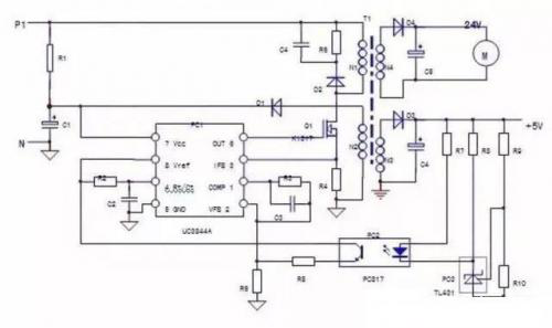
Simplified circuit diagram of switching power supply
Let’s familiarize ourselves with the picture, and see how there are several contexts in the circuit:
1) Oscillation circuit: the main winding N1 of the switching transformer, the drain-source of Q1, and R4 are the paths of the working current of the power supply; R1 provides the starting current; the self-powered windings N2, D1, and C1 form the power supply voltage of the oscillating chip. The normal operation of these three links is a prerequisite for the power supply to oscillate.
Of course, the 4-pin of PC1 is connected to the timing original R2, C2 and the PC1 chip itself, which also constitute a part of the oscillation circuit.
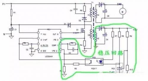
2) Voltage stabilization circuit: +5V power supply of N3, D3, C5, etc., R7~R10, PC3, R5, R6 and other components constitute the voltage stabilization control circuit.
Of course, PC1 chip and peripheral components R3 and C3 of pins 1 and 2 are also part of the voltage regulator circuit.
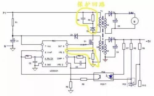
3) Protection circuit: The PC1 chip itself and the 3-pin peripheral component R4 constitute an overcurrent protection circuit; the D2, R6, and C4 components connected in parallel on the N1 winding constitute the back-pressure absorption protection circuit of the switch tube; in essence, the voltage feedback of the voltage regulator circuit Signal – voltage regulation signal, can also be regarded as a voltage protection signal, but the content of the protection circuit is not limited to the protection circuit itself, the start-up control of the protection circuit is often caused by the abnormality of the load circuit.
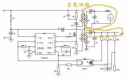
4) Load circuit: N3, N4 secondary windings and subsequent circuits are all load circuits. The abnormality of the load circuit will involve the protection circuit and the voltage stabilizer circuit, so that the two circuits can make corresponding protection and adjustment actions.
The vibration chip itself participates in and constitutes the first three circuits. If the chip is damaged, all three circuits will fail. The maintenance of the three or four circuits is carried out on the premise that the chip itself is normal. In essence, for example, the shock failure may not be caused by the damage of the components of the shock circuit. It may be the failure of the voltage regulator circuit or the abnormality of the load circuit, which causes the internal protection circuit of the chip to start control and stop the output of the PWM pulse. Each circuit cannot be completely isolated and repaired, and a faulty component is likely to have the effect of affecting the whole body.
Switching power supply circuits often show the following three typical fault phenomena:
1) The power supply voltage of the secondary load is 0V. After the inverter is powered on, there is no response, and the operation Display panel has no display. The 24V and 10V voltages of the control terminals are measured to be 0V. Check that the 530V voltage input by the switching power supply is normal, and it can be judged that the switching power supply is faulty. . The repair steps are as follows:
First, use the resistance measurement method to measure whether the switching tube Q1 has a breakdown short-circuit fault, and whether the current sampling R4 has an open circuit. The vulnerable component of the circuit is the switching tube. When it is damaged, the resistance value of R4 becomes larger or open circuit due to the impact. The series resistance of the G pole of Q1, the oscillation chip PC1 is often damaged by impact, and must be replaced at the same time; check whether the load circuit is short-circuited.
If the damaged parts are replaced, or no short-circuit components are detected, the power-on inspection can be performed to further determine whether the fault is in the oscillation circuit or the voltage-stabilizing circuit.
Detection method:
A. First check whether the starting resistor R1 is open or not. After it is normal, use the 18v DC power supply to directly feed it into the 7.5 pin of the UC3844 to power on the oscillation circuit separately. When measuring, the 8 pin should have a 5V voltage output; the 6 pin should have a voltage of about a few volts Output, indicating that the oscillation circuit is basically normal, and the fault is in the voltage regulator circuit.
If the measurement pin 8 has 5V voltage output, but the voltage of pin 6 is 0V, check the external R and C timing components of pin 8.8 and the peripheral circuit of pin 6.
If the 8-pin is measured and the 6-pin voltage is 0V, the UC3844 oscillator chip has been damaged and needs to be replaced.
B. Power on the UC3844 separately and short-circuit the input side of PC2. If the circuit starts to vibrate, it means that the fault is in the peripheral circuit of the input side of PC2; if the circuit does not vibrate, check the circuit on the output side.
2) The switching power supply oscillates intermittently, you can hear a “hiccup” or “squeak” sound, and the operation panel turns on and off. This is because the load circuit is abnormal, which causes the power supply to overload and causes the overcurrent protection circuit to act. Typical fault characteristics, The abnormal rise of the load current causes the excitation current of the primary winding to rise sharply, and a voltage signal of more than 1V is formed in the current sampling resistor R4, which makes the internal current detection circuit of UC3844 start to control, and the circuit stops; the overcurrent signal on R4 disappears, and the circuit starts to vibrate again. , and so on, and intermittent oscillation occurs.
Inspection Method:
A. Measure the resistance values at both ends of C5 and C6 of the power supply circuit. If there is a short-circuit and straight-through phenomenon, it may be that the rectifier diodes D3 and D4 are short-circuited; observe whether the appearance of C5 and C6 has bulging, liquid spray, etc., remove the measurement if necessary, and supply power. There is no abnormality in the circuit, it may be a short circuit fault in the load circuit.
B. Check that there is no abnormality in the power supply circuit, power on, and use the exclusion method to eliminate each power supply one by one, for example, unplug the fan power supply terminal, or unplug the +5V power supply terminal, if the power supply is normal, the device is damaged.
3) The power supply voltage of the load circuit is too high or too low, the oscillation circuit of the switching power supply is normal, the problem lies in the voltage regulator circuit, the output voltage is too high, the components of the voltage regulator circuit are damaged or inefficient, so that the feedback voltage amplitude is insufficient.
Inspection Method:
A. Connect a 10KΩ resistor in parallel at the output end of PC2, and the output voltage drops, indicating that the voltage regulator circuit on the output side of PC2 is normal, and the fault lies in PC2 itself and the circuit on the input side.
B. Connect a 500Ω resistor in parallel with R7, and the output voltage has dropped significantly, indicating that the optocoupler PC2 is good, and the fault is in the low efficiency of PC3 or the change of the external resistance element of PC3, otherwise, it is PC2 bad.
If the load power supply voltage is too low, there are three possible faults: the load is too heavy, causing the output voltage to drop; the voltage regulator circuit components are not good, causing the voltage feedback signal to be too large; the switching tube is inefficient, making the switching transformer insufficient energy storage.
Repair method:
a. Exclude the load circuits of the power supply branch one by one, and judge whether the voltage drops due to excessive load. For example, after cutting off the power supply of a certain channel, it returns to the normal value, indicating that the switching power supply itself is normal. Check the load circuit. If the output voltage is low, check the stability. pressure circuit.
b. Check the resistance R5~R10 of the voltage regulator circuit, there is no change in value; replace PC2 and PC3 one by one, if it is normal, it means that the replacement of the original is inefficient.
c. The replacement of PC2 and PC3 is invalid. The fault may be the low efficiency of the switch tube, or the low efficiency of the internal output circuit of UC3844. Replace the high-quality switch tube or UC3844 chip.
The Links: CM100RL-24NF MG75J1ZS50


