

Integrated bidirectional bridge with two RMS detectors for measuring RF power and return loss
“Directional couplers are used to detect RF power and are used in a wide variety of applications and can appear at multiple locations in the signal chain. This article discusses a new device from Analog Devices, the ADL5920, which integrates a broadband-based directional coupler with two RMS response detectors in a 5 mm × 5 mm surface-mount package. This device offers significant advantages over traditional discrete directional couplers, which require a difficult trade-off between size and bandwidth, especially at frequencies below 1 GHz.
“
By Eamon Nash and Eberhard Brunner
Directional couplers are used to detect RF power and are used in a wide variety of applications and can appear at multiple locations in the signal chain. This article discusses a new device from Analog Devices, the ADL5920, which integrates a broadband-based directional coupler with two RMS response detectors in a 5 mm × 5 mm surface-mount package. This device offers significant advantages over traditional discrete directional couplers, which require a difficult trade-off between size and bandwidth, especially at frequencies below 1 GHz.
In-line RF power and return loss measurements are typically accomplished using directional couplers and RF power detectors.
In Figure 1, bidirectional couplers are used in radio or test and measurement applications to monitor transmitted and reflected RF power. Sometimes it is desirable to embed RF power monitoring into a circuit, a good example is switching two or more signal sources into the transmit path (using RF switches or external cables).
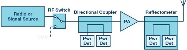
Figure 1. Measuring forward and reflected power in an RF signal chain.
Directional couplers have the important property of being directional, which means they can differentiate between incident and reflected RF power. When the incident RF signal passes through the forward path coupler (Figure 2) on its way to the load, a small fraction of the RF power (usually a signal 10 dB to 20 dB lower than the incident signal) is coupled into the RF detector. When both forward and reflected power are to be measured, an additional coupler must be used in the opposite direction to the forward path coupler. The output voltage signals of both detectors will be proportional to the forward and reverse RF power levels.
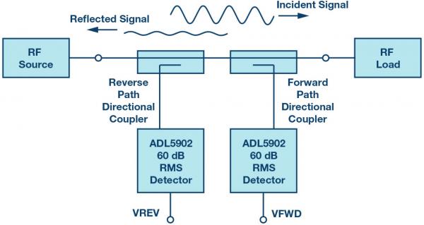
Figure 2. Typical RF Power Measurement System Using Directional Couplers and RF Detectors
The fundamental issue with surface mount directional couplers is the trade-off between bandwidth and size. While bidirectional directional couplers with a frequency coverage of one octave (that is, FMAX equals twice FMIN) are typically packaged in packages as small as 6 mm2, multi-octave surface mount directional couplers are much larger (Figure 3). Broadband connectorized directional couplers have multi-octave frequency coverage, but are significantly larger than surface mount devices.
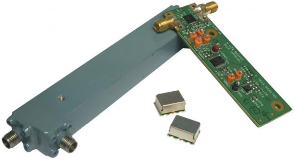
Figure 3. Connectorized directional coupler, surface mount directional coupler, and ADL5920 integrated IC with directional bridge and dual RMS detectors
Figure 3 also shows the ADL5920 evaluation board, a new RF power detection subsystem with up to 60 dB detection range in a 5 mm × 5 mm MLF package (the ADL5920 IC is located between the RF connectors). The functional block diagram of the ADL5920 is shown in Figure 4.
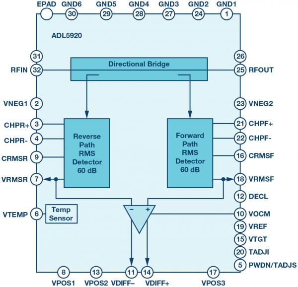
Figure 4. ADL5920 block diagram
Rather than utilizing directional couplers to detect forward and reflected signals, the ADL5920 employs a patented directional bridge technique for broadband and compact on-chip signal coupling. To understand how a directional bridge works, we need to review the Wheatstone bridge first.
Wheatstone bridge
The concept of a directional bridge is based on the Wheatstone bridge (Figure 5), i.e. the resulting differential voltage at equilibrium is zero. In a Wheatstone bridge, one resistance in one of the two branches is variable (R2), while the other two resistances (R1 and R3) are fixed. There are four resistors in total – R1, R2, R3 and Rx, where Rx is the unknown resistor. If R1 = R3, then VOUT = 0 V when R2 equals Rx. The bridge is considered to be in balance when the variable resistor has the proper value so that the voltage divider ratios on the left and right sides of the bridge are equal, resulting in a 0 V differential signal at the differential sense node that generates VOUT.
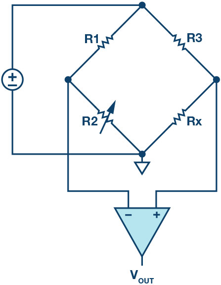
Figure 5. Wheatstone bridge
one-way bridge
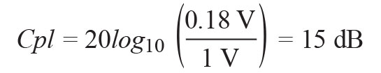
Figure 6 is a schematic of a unidirectional bridge that explains the basic operation of this device very well. The first thing to note is that the directional bridge needs to be designed for a specific Zo and minimize insertion loss.If RS = RL = R = 50Ω, then the bridge’s sense resistance is 5Ω, so the insertion loss (this voltage is further attenuated by 10/11 = 0.909, making the negative input of the differential amplifier 0.82V, the resulting differential voltage is (1 C 0.82 ) = 0.18 V. The effective forward coupling factor (Cpl) of the bridge is
 (1)
(1)
In terms of bridges, balanced means that when the signal is applied in the reverse direction (RFOP to RFIP), the VFWD detector (or Cpl port) will ideally see zero differential voltage, and when the signal is applied in the forward direction (RFIP to RFIP) RFOP), will see the maximum signal. In order to obtain maximum directivity in this structure, precision resistors are most important, so it is beneficial to integrate them.
In a unidirectional bridge, to determine the isolation required to calculate the return loss, the device needs to be flipped and the input signal applied to the RFOP. In this case, the bridge is balanced and the positive and negative inputs of the differential amplifier are equal because the same divider ratio 0.909 = (10R/(10R + R) = (R/(R+0.1R)) results in a differential voltage (V+ minus V-) = 0 V.
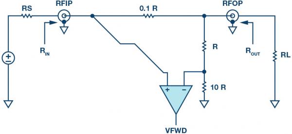
Figure 6. Simplified Unidirectional Bridge Circuit Diagram
two-way bridge
Figure 7 is a simplified diagram of a bidirectional bridge, similar to that used in the ADL5920. For a 50Ω environment, the unit resistance R is equal to 50Ω. Therefore, the sense resistor value of the bridge is 5Ω, while the resistance value of both shunt networks is about 1.1 kΩ.
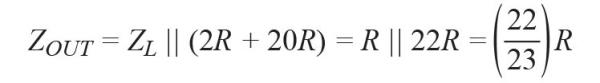
This is a symmetrical network, so when RS and RL are also equal to 50, the input and output resistances RIN and ROUT are the same and close to 50Ω.
When both source and load impedances are 50Ω, ohmic analysis of the internal network tells us that VFWD will be quite large compared to VREV. In practical applications, this corresponds to the maximum power transfer from the signal source to the load. This results in a very small reflected power, which in turn results in a very small VREV.
Next, we consider what happens if RL is infinite (open circuit) or zero (load short circuit). In both cases, if we repeat the ohmic analysis, we find that VFWD and VREV are roughly equal. This reflects an actual system with equal forward and reflected power under open circuit or load short circuit conditions. These situations are analyzed in more detail below.
Figure 7. Simplified Bidirectional Bridge Circuit Diagram
VSWR and reflection coefficient
A comprehensive analysis of errors in network analysis is too complex and beyond the scope of this article, but we would like to outline some basic concepts here. The application note “Directivity and VSWR Measurements” by Marki Microwave is an excellent article to refer to1.
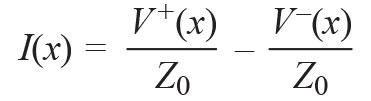
Traveling waves are an important concept for describing voltages and currents on transmission lines because they are a function of position and time. The general solution for voltage and current on a transmission line consists of a forward traveling wave and a reverse traveling wave as a function of distance x2.
![]() (2)
(2)
 (3)
(3)
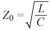
In Equation 2 and Equation 3, V+(x) represents the voltage wave traveling towards the load, while VC(x) represents the voltage wave reflected from the load due to mismatch, and Z0 is the characteristic impedance of the transmission line. In lossless transmission lines, Z0 is defined by the following classical equation:
 (4)
(4)
The most common Z0 for transmission lines is 50Ω. If such a line was terminated with a characteristic impedance, it would appear to be an infinitely long line to the 50Ω source, since any voltage waves traveling along the line would not generate any voltage waves that could be detected at the source or anywhere else on the line reflection. However, if the load is not 50Ω, there will be a standing wave along the line, which can be detected and is defined by the voltage standing wave ratio (VSWR).
More generally, the reflection coefficient is defined as:
![]() (5)
(5)
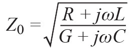
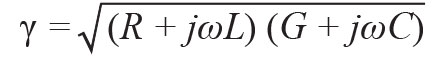
Where Γ0 is the load reflection coefficient, and γ is the propagation constant of the transmission line.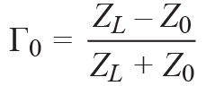 (6)
(6)
 (7)
(7)
 (8)
(8)
R, L, G, and C are the resistance, inductance, conductance, and capacitance per unit length of the transmission line, respectively.
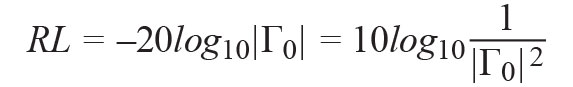
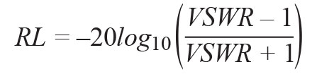
Return loss (RL) is the negative value of the reflection coefficient (Γ) in dB. This is important because reflection coefficient and return loss are often confused and used interchangeably.
 (9)
(9)
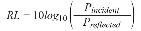
In addition to the above load mismatch, return loss has a very important definition, which is defined in terms of the incident and reflected power at the impedance discontinuity, as follows:
 (10)
(10)
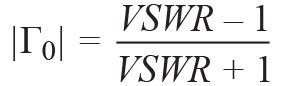
It is widely used in antenna design. The relationship between VSWR, RL and Γ0 is as follows:
 (11)
(11)
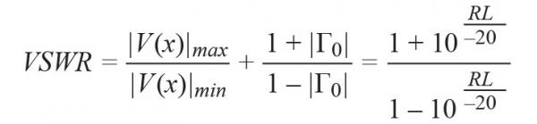 (12)
(12)
 (13)
(13)
Equation 14 and Equation 15 represent the maximum and minimum values of the standing wave voltage, respectively. VSWR is defined as the ratio of the maximum voltage to the minimum voltage on the wave. The peak and minimum voltages on the line are:
![]() (14)
(14)
![]() (15)
(15)
For example, in a 50Ω transmission line, if the peak amplitude of the forward traveling voltage signal is A = 1, and the line is matched to an ideal load, then |Γ0| = 0 and no standing waves (VSWR = 1.00), the peak voltage on the line is A = 1. However, if RLOAD is 100 Ω or 25 Ω, then |Γ0| = 0.333, RL = 9.542 dB, VSWR = 2.00, |V(x)|max = 1.333, and |V(x)|min = 0.666.
Figure 8 is a duplicate of Figure 7, but with the signal shown in the default forward configuration and with the traveling power wave indicated, with the reference plane at the load. At low frequencies, the wavelength is longer relative to the physical structure, the voltage and current are in phase, and the circuit can be analyzed according to Ohm’s law.
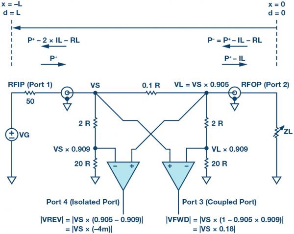
Figure 8. Simplified Bidirectional Bridge with Signals
The ports are defined as follows: input port (port 1) is RFIP, output port (port 2) is RFOP, coupled port (port 3) is VFWD, and isolated port (port 4) is VREV. Since the structure is symmetrical, the ports are inverted when the signal is reflected at ZL or applied to the RFOP.
With the load matched and the generator voltage connected to port 1 (RFIP), ZS = ZL = Z0 = R = 50 Ω,
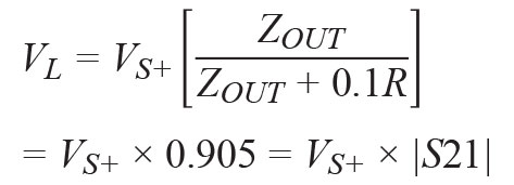 (16)
(16)
 (17)
(17)
VL/VS+ is the insertion loss LI or IL in dB.![]() (18)
(18)
The attenuation factor for the two parallel branches on either side of the 0.1×R main line resistance is:
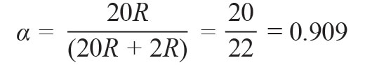 (19)
(19)
The |VREV| and |VFWD| equations in Figure 8 show the voltage values when a signal is applied in the forward direction. These equations point out the basic directional limit of the simplified schematic due to the suboptimal rejection (33 dB) of the isolated port.
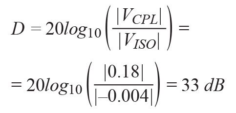 (20)
(20)
As can be seen from Figure 8, the directionality of a bidirectional bridge in the linear domain is determined by:
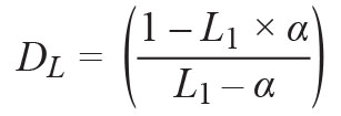 (twenty one)
This shows that in order to improve the directivity, α needs to be equal to the insertion loss L1.
In silicon wafers, the peak directivity is usually better than the diagram suggests (Figure 9).
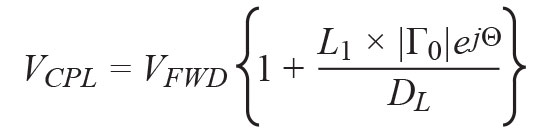
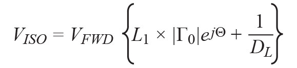
If ZL is not equal to ZO (normally), the coupled and isolated port voltages (complex) will be:
![]() (twenty two)
(twenty two)
![]() (twenty three)
(twenty three)
where VS+ is the forward voltage at port 1 (node VS) and VL- is the reflected voltage of the load at port 2 (node VL). Θ is the unknown phase of the reflected signal,
![]() (twenty four)
(twenty four)
Replace VL- in (22) and (23) with (24) and simplify the result with (21), additionally
![]() (25)
(25)
resulting in a very complex output voltage.
 (26)
(26)
 (27)
(27)
It can be seen from (26) and (27) that when DL>>1,
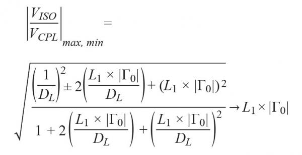 (28)
(28)
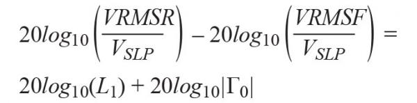
In the ADL5920, the voltages VREV and VFWD are mapped to the voltages VRMSR and VRMSF, respectively (VISO/VSLP) and (VCPL/VSLP), by two linear dB RMS detectors with 60 dB range.So the differential output VDIFF of the device (in dB) represents
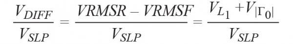 (29)
(29)
where the detector slope VSLP is about 60 mV/dB.
Using the voltage to dB mapping from (29) in (28),
 (30)
(30)
and using Equation 9 in Equation 30, we get:
![]() (31)
(31) ![]() (32)
(32)
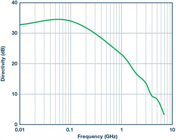
Figure 9. ADL5920 Directivity vs. Frequency Input level is 20 dBm.
Figure 10 shows the response of the forward power sense RMS detector when the ADL5920 is driven forward. Each curve corresponds to the output voltage versus frequency for a specific power level applied. The curve stops at 10 MHz, and operation down to 9 kHz has been verified. In Figure 11, the same data is shown as output voltage versus input power, with each trace representing a different frequency.
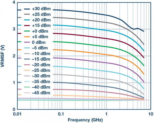
Figure 10. Typical Output Voltage vs. Frequency for Forward Path Detectors at Various Input Power Levels
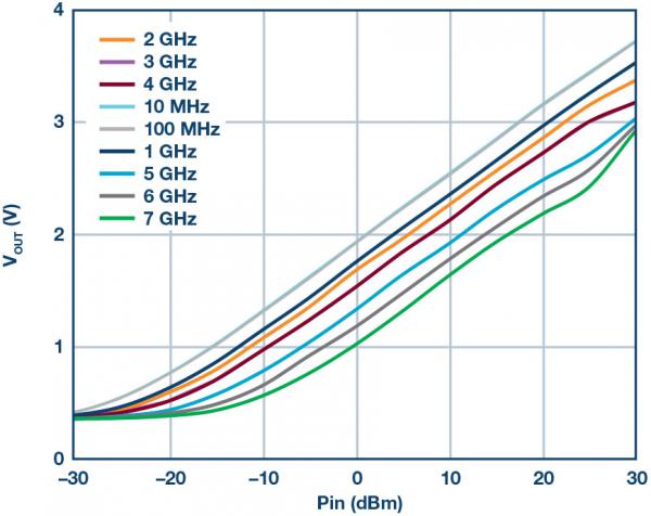
Figure 11. Typical Output Voltage vs. Input Power for a Forward Path Detector at Various Frequencies
When the RFOUT pin of the ADL5920 is terminated with a 50 Ω resistor, there should be no reflected signal. Therefore, the reverse path detector should not record any detected reverse power. However, since the directivity of the circuit is non-ideal and rolls off with frequency, some signal is detected in the reverse path. Figure 12 shows the voltages measured by the forward and reverse path detectors at 500 MHz when RFIN is swept and RFOUT is terminated with a 50Ω resistor. The vertical voltage difference between these traces is directly related to the directionality of the bridge.
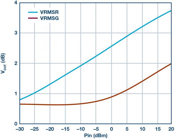
Figure 12. VRMSF and VRMSR Output Voltage vs. Input Power, 500 MHz, Bridge Driven from RFIN, RFOUT Terminated in 50 Ω.
Figure 13 shows the effect of changing the load on the forward power measurement. Applying the specified power level to the RFIN input, the load return loss on RFOUT varies from 0 dB to 20 dB. As expected, the power measurement accuracy is very good when the return loss is in the 10 dB to 20 dB range. But as the return loss drops below 10 dB, the power measurement error begins to increase. It is worth noting that with a return loss of 0 dB, the error is still within 1 dB.
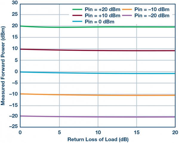
Figure 13. Measured forward power versus applied power and return loss of the load, measured at 1 GHz.
In Figure 14, the ADL5920 is used to measure the return loss of the load, again at 1 GHz. Apply a known return loss to the RFOUT port. Measure VRMSF and VRMSR and inverse return loss.
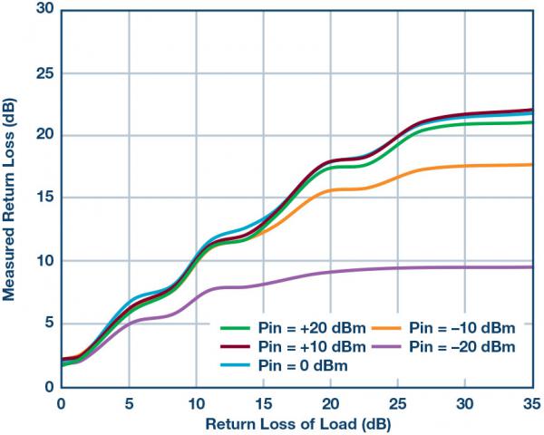
Figure 14. Measured Return Loss vs. Applied Return Loss and RF Power, Measured at 1 GHz
There are a few things to note about this graph. First, it can be seen that as return loss improves, the ability of the ADL5920 to measure return loss decreases. This is because the device is directional. Second, notice how the measurement accuracy decreases as the drive power decreases. This is due to the limited detection range and sensitivity of the ADL5920’s onboard RMS detector. The third point has to do with noticeable ripples in the traces. This is due to the fact that each measurement is made during a single return loss phase. If the measurement is repeated at all return loss stages, a series of curves will be produced whose vertical width will be approximately equal to the vertical width of the ripple.
application
With the ability to measure RF power and return loss online, the ADL5920 can be used in a variety of applications. Its small size means it can fit into many circuits without compromising space too much. Typical applications include online RF power monitoring (RF power levels up to 30 dBm where insertion loss is not critical). The return loss measurement function is typically used in applications that require monitoring of RF loads. This can be a simple circuit to check if the antenna has been damaged or broken (ie catastrophic failure). However, the ADL5920 can also measure scalar return loss in materials analysis applications. This is best for applications below about 2.5 GHz, where the directivity (and thus the measurement accuracy) is greater than 15 dB.
The ADL5920 evaluation board is available in two form factors, as shown in Figure 15. Shown on the left is a traditional evaluation board with the detector output voltage available via clip-on leads and SMA connectors. The evaluation board also includes a calibration path that can be used to calibrate the insertion loss of the FR4 board.
The evaluation board shown on the right is more integrated and contains a 4-channel 12-bit ADC (AD7091R-4). This evaluation board interfaces with the Analog Devices SDP-S USB interface board and includes PC software that calculates RF power and return loss, as well as performs basic power calibration routines.
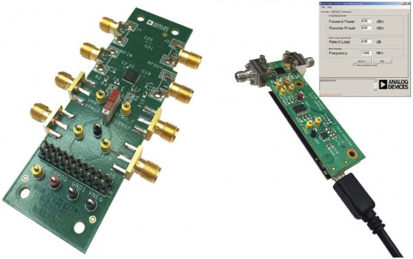
Figure 15. ADL5920 Evaluation Board Selection
references
1Doug Jorgesen and Christopher Marki. Directivity and VSWR measurements: Learn about return loss measurements. Marki Microwave, 2012.
2Guillermo Gonzalez. Microwave Transistor Amplifier Analysis and Design. Prentice-Hall, 1984.
3Eamon Nash. “Understanding, Operating, and Implementing Integrated Diode-Based RF Detector Interfaces.” Analog Devices, Inc., November 2015.
Thanks
Thanks to Steve Boyle for thoughtful analysis and constructive comments, and to Rob Hicks for creating the evaluation board. In addition, we are forever grateful to Peter Kearney for all his measurement work.
Eamon Nash [[email protected]


