
Design of a wireless transmission test system based on CC1100 and P89LPC922 microcontroller
“Wireless data communication technology is increasingly used in embedded systems. While simplifying wiring, it also makes data exchange more convenient. This article introduces a test system suitable for remote counting wireless transmission. The system is mainly composed of Texas Instruments (TI) CC1100 RF transceiver and Philips (Philips) microprocessor P89LPC922.
“
introduction
Wireless data communication technology is increasingly used in embedded systems. While simplifying wiring, it also makes data exchange more convenient. This article introduces a test system suitable for remote counting wireless transmission. The system is mainly composed of Texas Instruments (TI) CC1100 RF transceiver and Philips (Philips) microprocessor P89LPC922.
1 hardware design
(1) Overall scheme design
This design is composed of 1 host and 1 to 32 terminal slaves. After counting by the internal sensor, the slave transmits the data to the master wirelessly, and the master is responsible for the scheduling, Display, and configuration of the entire system.
(2) Microcontroller P89LPC922
The P89LPC922 chip has 8 KB Flash program memory, 1 KB erasable sector and 64-byte erasable page. It can erase a single byte. The instruction execution time only needs 2 to 4 clock cycles, and the instruction execution rate is 6 times that of The standard 80C51 device has configurable on-chip oscillator and RC oscillator, enhanced UART, baud rate generator, automatic address recognition and general interrupt functions.
(3) RF chip CC1100
The main features of CC1100 are: small size (20 pins, QLP 4 mm×4 mm), working frequency of 300~1000 MHz, high receiving sensitivity (110 dBm under 1.2 kb/s), and the maximum data transmission rate is up to 500 kb/s, low power consumption (15.6 mA in RX, 2.4 kb/s, 433 MHz), output power up to +10 dBm in all frequency bands; SPI interface, support ASK, OOK, 2-FSK, GF -SK and MSK modulation modes, with wireless wake-up (WOR) function, etc.
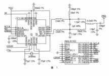
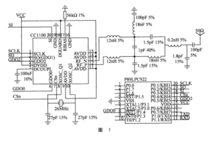
Since high frequency transceiver signals will interfere with the MCU part, the wireless communication part should be made of a separate PCB board and shielded. The connection of P89LPC922 and CC1100 is shown in Figure 1.
2 Software design
(1) Data packet format
The CC1100 data packet format includes the following parts: preamble, synchronization vocabulary, controllable data packet length, optional address byte, payload, and optional 2-byte CRC. It supports constant-length and variable-length data packet protocols, and its data length can reach 255 bytes. For longer data packets, an unlimited length data packet protocol must be used. This system uses a variable-length data packet format.
(2) Status and register settings
CC1100 has a built-in state machine to switch between different operating states (modes). The status changes are either through command filtering or through internal events (such as TX FIFO underflow). The current state can be obtained from the state register MARCSTATE. There are many registers in CC1100, which can be configured as required, and some of them need to be given by the software SmartRF Studio.
The 3 digital output pins SO (GDO1), GDO0, GDO2 of CC1100 can also be configured as required functional interfaces through the IOCFGX register. In the design, GDO0 IOCFGO=Ox06, the pin will be set to high level when the synchronization vocabulary is sent and received, and becomes low level when the data packet transmission ends. In addition, when the transceiver FIFO overflows, it will also become low. GDO2IOCFG2=Ox0B, the pin outputs a continuous clock, which can be used to detect whether CC1100 is working.
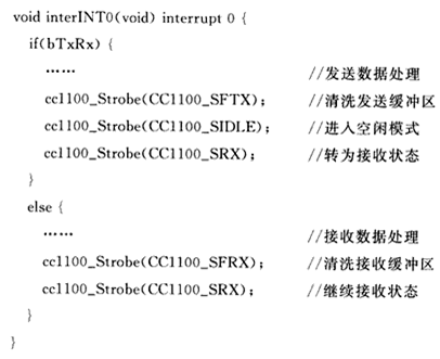
(3) Send and receive data
After CC1100 is powered on, the chip needs to be reset, register settings, power settings, etc. in sequence. Sending and receiving data can be interrupted through the GPO0 pin, and then processed according to different situations. The procedure is as follows:
3 communication protocol
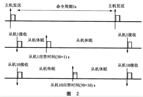
In most master-slave structure communication, the communication between the host and the slave is generally carried out by query, but when the number of slaves is large, the efficiency is not high. Therefore, it is necessary to design a fast and practical communication mode. Time division multiple access (time division multiple access) is to divide the time into non-overlapping time periods (frames), and then divide the frame into non-overlapping time slots (channels), and have a one-to-one correspondence with users; distinguish according to time slots User signals from different addresses to complete multiple access connections. Time Division Multiple Access is abbreviated as TDMA.
According to the above definition, in the design, the master uses the method of sending commands regularly, and each slave allocates a time period for communicating with the master. The selection of the time period should be determined according to the number of slaves, the synchronization time, and the communication rate. The specific agreement is as follows:
The master sends commands to the terminal slaves at regular intervals. The commands contain the time of the next synchronization and other required information. The command cycle can be defined by itself, where the command cycle is 1 s.
After the slave receives the command from the master, it synchronizes its own clock first, and then takes the corresponding action.
① For commands that do not respond, the slave immediately enters the dormant state, and only exits dormancy 2 ms in advance of the time when the next host command is received.
②For commands that have a response, the slave will delay (N×30) ms to respond to the master after receiving the master command. Before there is a response, the slave will enter sleep first, but wake up 2ms earlier before the response time comes. , Ready to answer. The response time of the slave is 1~25 ms, and the remaining 5 ms is to separate one time period from another (namely, protection time). When the response is over, it will delay 2 ms to enter sleep.
③When the slave fails to synchronize with the master, the CC1100 electromagnetic wave activation function should be turned on to search for the master information.
Among them, N is the slave address number, the setting range is 1 to 32, and the specific communication protocol is shown in Figure 2.
Concluding remarks
The wireless data communication scheme introduced in this article is suitable for industrial signal monitoring, wireless instrumentation testing, building intelligent systems, etc. It is cost-effective and the proposed communication protocol has strong real-time and reliability. Field work shows that in the counting test system, no communication error occurred within 100 m, which met the test requirements.
The Links: B141XG08-V1 CM100DU-12H IGBTMODULE


