Analysis of the Tutorial of Virtual Grounding Scheme in Modern Circuit Design
“This note is a tutorial on designing virtual grounds for modern circuits. In order to keep up with the increasing complexity of today’s systems, the old track splitting technology is now slowly being replaced by newer virtual ground methods.
“
This note is a tutorial on designing virtual grounds for modern circuits. In order to keep up with the increasing complexity of today’s systems, the old track splitting technology is now slowly being replaced by newer virtual ground methods.
The railway split is creating an artificial virtual ground as a reference voltage. It is used to set the signal to match the “sweet spot” of the op amp. The operational amplifier has the most linear and distortion-free characteristics at this optimal position. Usually, the best location occurs near the center between the single power rail and ground. In the case of many signals, the virtual ground can control the channel DC error when multiplexing or switching signals.
“Rail Splitter” is the nickname of US President Abraham Lincoln. The name comes from his humble background-as a young man, he chopped wood to make fences. To the extent that most of us are in contact with wood, we are playing with Lincoln Logs® toys. Those are the brown round notched wood we used to build the cabin style building. Because Mr. Lincoln was born in a cabin, the log is also named after him. He is also the only American president who holds a US patent (#6469).
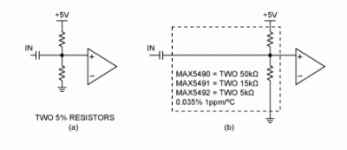
Although interesting, this is not the kind of railroad split we are discussing. In Electronic circuits, the rail is the common power and ground connection for all components. Many components, such as amplifiers and analog-to-digital converters (ADCs), need to bias the signal so that it can be centered between the power rails. This is a virtual ground point, also known as the “orbital splitter”. In early electronic circuits, there were positive and negative power supplies, so signal biasing was easy-we just used the ground as a reference. A typical modern circuit uses only one power supply. For example, if we only have a +5 V rail and ground, we may need a 2.5 V center offset point (virtual ground). If we only need an inaccurate bias point, two 5% resistors are enough, as shown in Figure 1a. If the bias point is critical, set the IF bias point.
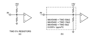
In the application shown in Figure 2, we want to match the DC voltage between the channels to minimize the settling time after the switching point. For this application, we need multiple matching bias points.
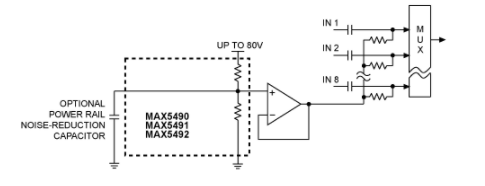
Multiple precision matching bias power supplies.
In the case that the MAX5490/MAX5491/MAX5492 do not require 0.035% accuracy, we recommend using the circuit shown in Figure 3. In this circuit, only 1% accuracy is needed, but it is still important that all bias points are the same.
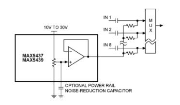
An integrated virtual ground rail separator.
MAX5437/MAX5439 are 128-step digital potentiometers with an unspecified operational amplifier, as shown in Figure 4. If we ignore the three SPI™ serial port pins by grounding them, the MAX5437/MAX5439 will power up at mid-range with a tolerance of ±1%. The end-to-end resistance of the MAX5437 is 50 kΩ, and the end-to-end resistance of the MAX5439 The end-to-end resistance is 100 kΩ. They are all available in a 14-pin TSSOP package.
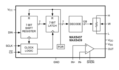
MAX5437 and MAX5439 digital potentiometers.
MAX5437 and MAX5439 each form a very common virtual ground. If we have a known asymmetric signal waveform, we can change the position of the potentiometer, and then the DC bias voltage can be any of 128 different levels. If we want the voltage step to be smaller (more precise), we can add resistors to the top and bottom of the pot to move the 128 steps to a smaller range. Another option is to use a voltage reference to set the potentiometer terminal voltage.
Since the MAX5437/MAX5439 operational amplifiers are unconfigured, we can choose to adjust the gain and offset, provide inversion, and even build filters. MAX5437/MAX5439 can be powered by ±15 V. In addition, these op amps have a shutdown function pin, which means that the output can be used to multiplex multiple parts together. In systems where the ADC needs to add a jitter signal to the signal, we can also add a jitter signal. By injecting the jitter signal into Figure 3, where the noise reduction capacitor is grounded, we automatically apply the jitter to all multiplexer inputs. Because the MAX5437/MAX5439 switch in a non-interference manner, the potentiometer can be moved between the taps at will. Most importantly, the temperature coefficient is only a 5 ppm/°C ratio.
Our track divider is as versatile as Mr. Lincoln, but in the past 160 years, times have changed. Today, Mr. Lincoln will be surprised at our fast world. We communicated quickly for all ages through the Internet and telephone, fast food, instant coffee, fast cars, winter fruits (flying from the southern hemisphere), and sometimes even the microwave oven seemed to take too long. The strange thing is that Mr. Lincoln’s patent application and authorization only took 73 days, while today’s patent processing takes several years. His patents are only three pages; today, it is difficult to find patents with fewer than ten pages, and some are even hundreds of pages long. That’s it for speed, progress, and the much-touted paperless office! However, in our constantly changing electronic virtual ground.
The Links: NL6448BC26-27 A3PN030-ZVQG100


