
“In radio frequency (RF) applications such as automotive radar, 5G cellular, and the Internet of Things, the use of radio frequency sources by Electronic systems is increasing day by day. All these RF sources need to try to monitor and control the RF power level without causing loss of transmission lines and loads. In addition, some applications require high-power transmitter output, so designers need to find ways to monitor the output signal instead of directly connecting sensitive instruments to avoid damage caused by high signal levels.
“
In radio frequency (RF) applications such as automotive radar, 5G cellular, and the Internet of Things, the use of radio frequency sources by electronic systems is increasing day by day. All these RF sources need to try to monitor and control the RF power level without causing loss of transmission lines and loads. In addition, some applications require high-power transmitter output, so designers need to find ways to monitor the output signal instead of directly connecting sensitive instruments to avoid damage caused by high signal levels.
There are also many other challenges: how to determine the characteristics of the radio frequency load (such as an antenna) in a wide frequency range; how to monitor the load change and the standing wave ratio when the transmitter is in the broadcasting state to prevent high reflected power and amplifier damage, etc. .
These requirements and challenges can be solved by simply connecting the directional coupler to the transmission line. This method can accurately monitor the RF energy flow in the line while reducing the power level by a known fixed amount. During the sampling process, the directional coupler has minimal interference to the main line signal. In addition, the forward and reflected power can be separated, allowing the return loss or standing wave ratio to be monitored, thereby providing feedback on load changes during broadcast.
This article discusses the operation of the directional coupler, introduces three topologies and related products from Anaren, M/A-Com and Analog Devices. Then, this article introduces typical product features in detail and demonstrates effective usage methods.
What is a directional coupler?
A directional coupler is a measuring device that can be connected to the transmission line between the RF source and the load such as signal generators, vector network analyzers, and transmitters to measure the RF power (forward component) from the RF source to the load. And the power reflected from the load back to the RF source (reflected component). If the forward and reflected components are measured, the total power, the return loss of the load and the standing wave ratio can be calculated.
Schematic symbols for three-port (left) and four-port directional couplers (right). (Picture: Digi-Key Electronics) Normally, the power supply is connected to the input port of the coupler, and the load is connected to the output or transmission port. The output of the coupling port is the attenuated forward signal. The attenuation value is shown in the schematic diagram of the three-port device. In a three-port device, the isolated port is internally terminated; in a four-port device, the output of this port is proportional to the reflected signal. The arrows in the schematic symbols indicate component paths. For example, in a four-port configuration, the input port points to the coupled port, indicating that it receives the forward component, and the output port is connected to the isolated port, which is used to read the reflected signal. The port number is not standardized and varies from manufacturer to manufacturer. However, the port naming of each vendor is relatively uniform.
The coupler is a symmetrical device, and the connection of each port is interchangeable. For a three-port device, reversing the input and output ports will make port 3 an isolated port. In a four-port device, reversing the input and output ports will interchange the coupling and isolation ports.
The output of the coupler is a radio frequency signal. The output of the coupling and isolation ports is usually connected to a peak or RMS detector, which produces baseband signals related to the forward and reflected power levels. The combination of directional coupler and related detector constitutes a reflectometer.
In some cases, two directional couplers are connected back to back to form a dual directional coupler, so as to minimize the leakage between the coupled port and the isolated port.
Directional coupler specifications
Directional couplers have several key characteristics, including bandwidth, rated input power, insertion loss, frequency flatness, coupling coefficient, directivity, isolation, and residual voltage standing wave ratio (VSWR).
Bandwidth: The bandwidth of the coupler represents the frequency range, in hertz. In this frequency range, the coupler can work within the specification range.
Rated input power: For continuous wave (CW) and pulse input signals, the coupler has the maximum rated input power, in watts. This value represents the maximum power that the device can handle without degrading performance or causing physical damage.
Insertion loss: used to describe the power loss caused by the device accessing the main transmission path, in decibels (dB) as the unit.
Frequency flatness: Frequency flatness refers to the amplitude response change of the main transmission path within a specific bandwidth of the device. This value is a function of the frequency change of the input signal, in dB.
Coupling coefficient: The coupling coefficient refers to the ratio of the input power to the output power of the coupling port when all ports of the coupler are correctly terminated, in dB. This is one of the main characteristics of the directional coupler. The output of the coupling port is proportional to the power level of the direct path (from input to output), and the proportional coefficient is a known value. The coupling port output can be connected to other instruments such as oscilloscopes without the risk of instrument overload.
Isolation: When all ports are correctly terminated, the power ratio of the input port to the isolated port, in dB.
Directivity: When all ports are correctly terminated, the power ratio of the coupled port to the isolated port, in dB. For a three-port coupler, two power measurements are usually performed: one is performed under normal positive termination, and the other is performed under the condition of reverse connection of input and output ports. This specification is used to measure the degree of separation of the forward and reflected components; generally, the greater the directivity, the better the performance of the coupler. Directivity cannot be measured directly, but can only be calculated by the measured values of isolation and reverse isolation.
Residual VSWR: The standing wave ratio measured when all ports of the coupler are properly terminated. This value is used to measure the inherent impedance matching of the coupler.
Directional coupler topology
Directional coupler design can be implemented in several ways, of which the three most common topologies are RF transformers, resistive bridges, and coupled transmission lines. The topology based on the RF transformer uses two RF transformers (Figure 2). Among them, the transformer T1 is used to detect the main line current between the input and the load. The other transformer T2 is used to detect the ground voltage of the main line. The coupling coefficient depends on the transformer turns ratio N.
The directional coupler topology based on the RF transformer uses two RF transformers to detect the forward and reflected components on the main line. (Picture: Digi-Key Electronics) By combining the induced voltage of each transformer on the coupling line, and then adding the results, the theoretical operation analysis of this type of directional coupler can be performed (Figure 3). Vin is the forward voltage and VL is the reflected voltage.

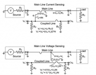
Figure 3: Analysis of the transformer-based coupler by analyzing the voltage of two transformers on the coupling line. (Picture: Digi-Key Electronics) In the above figure, in order to calculate the coupling port voltage (VF’) and isolation port voltage (VR’) on the coupling line, a current detection transformer is connected, but the voltage detection transformer is removed. Similarly, the current detection transformer is removed in the figure below, and a voltage detection transformer is connected to the port to calculate VF” and VR”. The coupling port voltage VF can be obtained by adding VF’ and VF”:
The isolated port voltage is equal to the reflected voltage divided by the negative of the transformer turns ratio. The negative sign indicates that the reflected voltage is 180° out of phase with the forward voltage.
This type of directional coupler performs well in a wide frequency range. For example, M/A-Com’s MACP-011045 has a bandwidth range of 5 to 1225 MHz. This transformer-based coupler has a coupling coefficient of 23 dB and a rated power of 10 W. Isolation depends on frequency. When the frequency ranges from below 30 MHz to above 1 GHz, the corresponding isolation range is 45 dB to 27 dB. The device uses a surface mount package with dimensions of 6.35 mm x 7.11 mm x 4.1 mm, so it is compatible with most wireless applications.
Couplers based on coupled transmission lines are composed of coaxial cables or printed circuit transmission lines. This mechanism aligns two or more transmission lines (typically 1/4 of the wavelength in length) tightly so that a small amount of controlled signal power leaks from the main line to one or more coupled lines. An example of a dual directional coupler using coupled transmission lines. The length of the transmission line is usually 1/4 of the center wavelength of the design band. (Picture: Digi-Key Electronics) Input connection port 1, and most of the power is transferred to the load connected to port 2. A small amount of power is coupled to the auxiliary line connecting ports 3 and 4. Port 3 is a coupling port. The power level of this port accounts for a fixed percentage of the input power. The coupling coefficient can be used to describe the power of the coupling port and depends on the geometric arrangement of the coupling line. The reflected power is coupled to port 4 (isolated port).
Anaren’s 11302-20 is a typical coupled transmission line directional coupler with a frequency range of 190 to 400 MHz and a processing power of up to 100 W. The nominal coupling coefficient of this device is 20 dB, and the insertion loss is 0.3 dB. The package adopts a surface mount format with a size of 16.51 x 12.19 x 3.58 mm, which can be used to monitor the power level and VSWR measurement of medium power transmitters. The size of this type of coupler is related to the frequency range, the lower the operating frequency, the longer the length. Therefore, it is often used in UHF and high frequency applications, and the corresponding device size is small.
The last directional coupler topology is the directional bridge, and the circuit is related to the classic Wheatstone bridge. Analog Devices’ ADL5920 RMS and VSWR detector uses this topology (Figure 5).
Simplified schematic of the bidirectional bridge used in Analog Devices’ ADL5920 RMS and VSWR detector. When all ports are properly terminated, the analysis shows that the directivity is 33 dB, and the calculation is shown in the figure) ADL5920 uses a resistive bridge to separate the forward and reflected voltages on the transmission line. As shown in the figure, when all ports are correctly terminated, the theoretical directivity of the low-frequency device can be calculated. The directivity obtained is 33 dB. In the bridge, the VREV and VFWD output signals are transmitted to the RMS cascade detector (dynamic range of 60 dB). The detector output can be read linearly in dB. The third output voltage derived from the difference between the forward output and the reflected output is proportional to the return loss, in dB. The frequency range of the bridge-based coupler is 9 kHz to 7 GHz, and when the matched load is 50 Ω, the rated power is 33 dBm (2 W). When the frequency range is 10 MHz to 7 GHz, the corresponding insertion loss range is 0.9 dB to 2 dB. The device uses a 5 x 5 mm surface mount package with a thickness of 0.75 mm.
Analog Devices has launched the ADL5920-EVALZ evaluation board for ADL5920. This fully equipped evaluation board requires a 5 V, 200 mA power supply. The input, output, and main output are all connected via 2.92 mm connectors. The following schematic shows the typical connections required by the ADL5920 (Figure 6). This evaluation board is an ideal tool to easily try ADL5920.
The ADL5920-EALZ evaluation board schematic shows the typical connections required for Analog Devices’ ADL5920 bidirectional RMS and VSWR detector. (Picture: Analog Devices) The directional coupler realized by the resistance bridge provides the widest frequency range, which is basically close to direct current (DC). Couplers based on transformers and transmission lines have more bandwidth limitations but higher power ratings.
Any of the above devices can extract input power samples for use in signal monitoring circuits. With the help of traditional instruments such as an oscilloscope or spectrum analyzer to measure the obtained samples, the power level, frequency and modulation degree can be determined. Data can also be integrated into the feedback loop to adjust the output to stay within the desired range.
The load status can be represented by the voltage standing wave ratio (VSWR). Using the output of the coupled port and the isolated port (that is, the forward voltage and the reflected voltage), the load VSWR of the output port can be calculated.
Summarize
For designers of radio frequency systems, directional couplers are very useful measurement devices. It not only provides an amplitude ratio view of the RF power level, but also separates the forward and reflected signal components, which facilitates the analysis of load characteristics. As mentioned above, there are currently three common coupler topologies that can provide these outputs, not only in a small package, but also compatible with wireless devices.
The Links: G121X1-L03 BSM150GB170DLC

