
What is the difference between the switching power supply Buck circuit CCM and DCM operating modes?
“During a switching cycle, the Inductor current never reaches 0. In other words, the inductor never “resets”, which means that the magnetic flux of the inductor never returns to 0 during the switching cycle. When the power tube is closed, there is still current flowing in the coil.
“
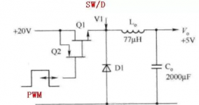
Buck switching regulator
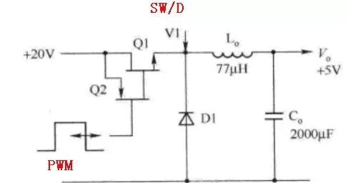
figure 1
Definition of CCM and DCM
1) CCM (Continuous Conduction Mode), continuous conduction mode: in one switching cycle, the inductor current never reaches 0. In other words, the inductor never “resets”, which means that the magnetic flux of the inductor never returns to 0 during the switching cycle. When the power tube is closed, there is still current flowing in the coil.
2) DCM, (Discontinuous Conduction Mode), discontinuous conduction mode: During the switching cycle, the inductor current always reaches 0, which means that the inductor is properly “reset”, that is, when the power switch is closed, the inductor current is zero.
3) BCM (Boundary Conduction Mode), Boundary Conduction Mode: The controller monitors the inductor current, and once it detects that the current is equal to 0, the power switch is closed immediately. The controller always waits for the inductor current to “reset” to activate the switch. If the inductor value current is high and the off-ramp is fairly flat, the switching period is prolonged, so the BCM converter is a variable frequency system.
Figure 2 shows three different modes of operation through the inductor current curve.
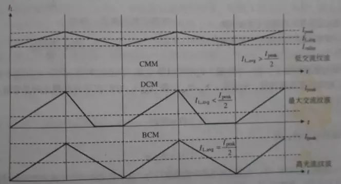
Figure 2 Three modes of inductor operation: CCM/DCM/BCM
The midpoint amplitude of the current ramp is equal to the average value of the DC output current Io, and the difference between the peak current Ip and the valley current Iv is the ripple current.
CCM working mode and characteristics
According to the definition of CCM, the waveform of the buck converter working in continuous mode is tested, as shown in Figure 3 below.
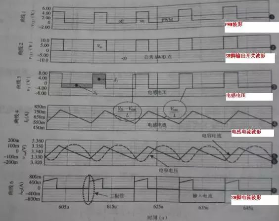
image 3
Waveform 1 represents the PWM pattern, triggering the switch to be on and off. When the switch SW is turned on, the voltage on the common point SW/D is Vin. On the contrary, when the switch is turned off, the voltage of the common point SW/D will swing to negative, and the inductor current will provide a bias current to the diode D at this time, and a negative step-down – freewheeling effect will appear.
Waveform 3 depicts the change in voltage across the inductor. At the equilibrium point, the average voltage across the inductor L is 0, and S1+S2=0. The area of S1 corresponds to the product of voltage and time when the switch is on, and the area of S2 corresponds to the product of voltage and time when the switch is off. S1 is simply the rectangle height (Vin-Vout) times D, and S2 is also the rectangle height-Voutt times (1-D)Tsw. If S1 and S2 are summed and averaged over the entire period Tsw, we get:
Simplifying the above equation can get to the step-down DC transfer function of the CCM:
It can be seen from the above formula that Vout varies with D (duty cycle).
In fact, let’s look at the last waveform above. When the switch is closed, the current waveform at point SW/D has a large peak. The voltage waveforms actually measured by the voltage chips ACT4065 and ACT4065A are shown in Figure 4 and Figure 5. There are two specific reasons as follows.
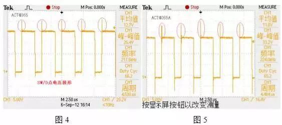
First, because when the switch is closed, Vin is applied to the cathode of the diode, which suddenly interrupts the conduction cycle of the diode. For a PN diode, it is first necessary to change the PN junction during forward conduction to the PN junction when it is electrically neutral to remove all minority carriers. It takes a certain amount of time for the diode to remove all the injected charge to return to its off state, and before fully recovering, it exhibits short-circuit behavior. For Schottky diodes, there is a metal semiconductor silicon junction, which has no recovery effect, however, there is a large parasitic capacitance, and there is also a junction capacitance. When the diode is turned on, once discharged, SW quickly acts on the voltage Vin through the discharge capacitor, resulting in a current spike. So slowing down the time to close the switch SW will help reduce the peak current.
Second, it is related to the shape of the current. From the image you can see that the output ripple (capacitor current waveform) is small. The output ripple is smooth and “pulse free”. It means that the output current signal can be well accepted by the subsequent circuit, that is, there is less pollution in the power supply. In addition, the input current not only has spikes, but also looks like a square wave. If the value of the inductance L tends to infinity, the waveform of the input current is a real square wave. Therefore, this current is a “pulsating” current that contains a large amount of contamination and is more difficult to filter than a typical sinusoidal shaped current.
Square wave: It consists of the odd harmonics of a sine wave, that is, it consists of frequencies such as sine 1, 3, 5, 7…n.
There are also spikes at the moment when the switch is turned off. I think it should also be related to the parasitic capacitance and junction capacitance of the diode and the SW pin.
From the above, the characteristics of the CCM buck converter can be summarized:
1) D is limited to less than 1, and the output voltage of the buck converter is always less than the input voltage;
2) If various ohmic losses are ignored, the transformation coefficient M has nothing to do with the load current;
3) By changing the duty cycle D, the output voltage can be controlled;
4) The buck converter works in CCM, which will bring additional losses. Because the reverse recovery charge of the freewheeling diode takes time to consume, this is an additional loss burden for the power switch;
5) The output has no pulse ripple, but there is a pulse input current.
DCM working mode and related features
The switching devices work in CCM mode when the load current is large, but when the load current decreases, the ripple current will decrease as a whole, as shown in Figure 2, when the load current is reduced to half the peak-to-peak value of the harmonics, that is Io=(Ip-Iv)/2, the lowest point of the ramp just drops to zero, at this lowest point, the inductor current is zero and the inductor energy storage is zero. If the inductor load current is further reduced, the inductor will enter DCM operation, the voltage and current waveforms will change greatly as shown in Figure 6 below, and the transfer function will change greatly.
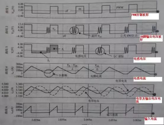
Image 6
From waveform 4, it can be seen that the inductor current drops to 0, causing the freewheeling diode to turn off. If this happens, the left end of the inductor is open. Theoretically, the voltage at the left end of the inductor should return to Vout, because there is no more current in inductor L and no oscillation occurs. However, due to the existence of many parasitic capacitances around, such as the parasitic capacitance of diodes and SW, an oscillation circuit is formed. Like curves 2 and 3, a sinusoidal signal appears and disappears after a few cycles, which is related to resistance damping. However, there may be differences in actual testing. For example, in the ACT4065A test, the waveform of SW/D is tested, but the oscillation is in the middle, as shown in Figure 7 below, which is in DCM mode.
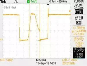
Figure 7
The buck transformer controls the output voltage at a constant value over the entire load range, even if the inductor enters discontinuous operation. Therefore, it is easy to make us misunderstand that the inductor entering the discontinuous operation mode has no effect on the circuit operation. In effect, the transfer function of the entire circuit has changed, and the control loop must adapt to this change.
For a Buck regulator, it’s no problem for the inductor to go into discontinuous mode. Before entering discontinuous mode, the DC output voltage Vout=Vin·Ton/T. Note that this formula has nothing to do with the load current parameter, so when the load changes, there is no need to adjust the duty cycle D, and the output voltage remains constant. In fact, when the output current changes, the on-time also changes slightly because the on-voltage drop and inductor resistance of Q1 change slightly with the current, which requires Ton to make appropriate adjustments.
After entering the DCM operation, the transfer function will change, the transfer function of the CCM will no longer apply, and the on-time of the switch will decrease with the decrease of the DC output current. The following is the transfer function in DCM operating mode, the duty cycle is related to the load current, namely:
Because the control loop wants to control the output voltage to be constant, the load resistance R is inversely proportional to the load current. Assuming that Vout, Vin, L, T are constant, in order to control the voltage to be constant, the duty cycle must vary with the load current.
At the critical switching current, the transfer function transitions from CCM to DCM. When working in CCM, the duty cycle remains constant and does not change with the load current; when working in DCM, the duty cycle changes as the load current decreases.
From the above, the characteristics of the DCM buck converter can be summarized:
1) M depends on the load current;
2) For the duty cycle figured out, the transfer coefficient M under DCM is larger than that of CCM, and when the load current is low and working in deep DCM, M can easily reach 1.
CCM vs DCM
1) Working in DCM mode, which can reduce power consumption, the conversion efficiency of DCM mode is higher, which belongs to complete energy conversion;
2) Working in DCM mode, the output current ripple is larger than CCM;
3) Working in DCM mode, when the inductor current is 0, oscillation will occur;
4) When working in CCM mode, the output voltage has nothing to do with the load current. When working in DCM mode, the output voltage is affected by the load. In order to control the voltage to be constant, the duty cycle must change with the change of the load current.
The Links: PS11035 6MBI50UA-120

