
Basic principles and typical architecture applications of automotive power supply design
“Conflicting design requirements such as high reliability, low cost, and extremely short development cycles are forcing power supply designers to adopt new, ground-breaking technical solutions that are not available in traditional automotive power supply designs.
“
Conflicting design requirements such as high reliability, low cost, and extremely short development cycles are forcing power supply designers to adopt new, ground-breaking technical solutions that are not available in traditional automotive power supply designs.
Basic principles of automotive power supply design
Most automotive power architectures need to follow six basic principles:
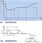
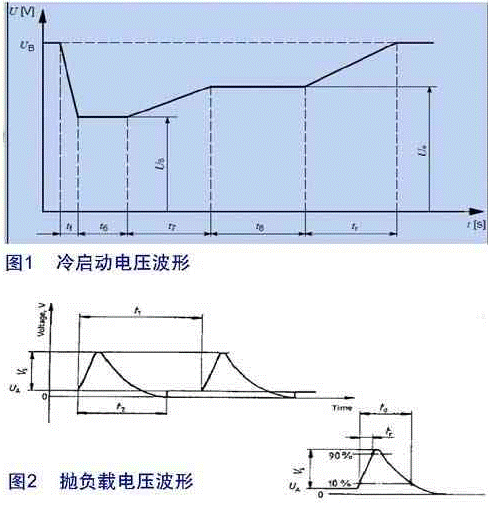
1) Input voltage range VIN: The instantaneous fluctuation range of the 12V battery voltage determines the input voltage range of the power conversion IC.
The ISO7637-1 industry standard defines the voltage fluctuation range of automotive batteries. The waveforms shown in Figure 1 and Figure 2 are the waveforms given by the ISO7637 standard, which show the critical conditions that high-voltage automotive power converters need to meet.
2) Heat dissipation considerations: Heat dissipation needs to be designed according to the minimum efficiency of the DC-DC converter.
Well-designed switching power converters are usually more efficient than linear regulators, and the higher conversion efficiency can eliminate large heat sinks and large package outlines in power supply designs. Most inexpensive small exposed pad packages can dissipate 2W at 85°C and 1W at 125°C. High-power designs above 20W have stricter thermal management requirements and need to adopt a synchronous rectification architecture. A high-efficiency external MOSFET controller helps improve the heat dissipation capability of the power supply.
3) Quiescent operating current (IQ) and shutdown current (ISD): With the rapid increase in the number of Electronic Control Units (ECUs) in automobiles, the total current drawn from the car battery is also increasing. Some ECU units keep working even when the engine is running and the battery is depleted. In order to keep the quiescent operating current IQ within a controllable range, most OEMs begin to limit the IQ of each ECU. For example, the requirement proposed by the European Union is: 100μA/ECU.
4) Cost control: OEMs need to compromise on module costs, development/certification costs, time-to-market and specifications. In order to ensure the optimal design under the premise of cost permitting, the bill of materials of the power supply part may occupy a very important position in terms of cost.
Module cost is related to PCB type, heat sink, device layout and its design factors. For example, replacing a CM-3 single-layer board with an FR-4 4-layer board can make a big difference in heat dissipation from a PCB.
5) Location/Layout: PCB and component layout in power supply design can limit the overall performance of the power supply.
Structural design, board layout, noise sensitivity, interconnection issues with multilayer boards, and other layout constraints can constrain the design of high-chip integrated power supplies. Using a point-of-load power supply to generate all the necessary power also incurs high costs, and it is not ideal to pack many components on a single chip. Power designers need to balance overall system performance, mechanical constraints, and cost against specific project needs.
6) Electromagnetic radiation: Electromagnetic interference generated by one working circuit may cause another circuit to fail to function properly. For example, interference from radio channels can cause airbags to malfunction. To avoid these negative effects, OEMs have established maximum electromagnetic radiation limits for ECU units.
To keep electromagnetic emissions (EMI) under control, the type of DC-DC converter, topology, selection of peripheral components, board layout, and shielding are all important. After years of accumulation, power IC designers have developed various techniques to limit EMI. External clock synchronization, operating frequency higher than AM modulation band, built-in MOSFET, soft switching technology, spread spectrum technology, etc. are all EMI suppression solutions introduced in recent years.
Application and Power Requirements
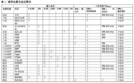
The basic architectural choice for most system power supplies should start with the power supply requirements and the battery voltage transient waveform defined by the automaker. Requirements for current should be reflected in the thermal design of the board. Table 1 summarizes the circuit and voltage requirements for most designs.
Topology of Universal Power Supply
Four commonly used power architectures are listed here, summarizing the typical design architectures in the automotive field in the last three years. Of course, users can achieve specific design requirements in different ways, and most solutions can be summarized as one of these four structures.
plan 1
This architecture provides a flexible design for optimizing the efficiency, layout, PCB heat dissipation, and noise specifications of the DC-DC converter. The main advantages of option 1 are:
Increase flexibility in nuclear design. Even if it is not the lowest cost/highest efficiency solution, adding a stand-alone converter can help reuse the original design.
Helps make rational use of switching power supplies and linear regulators. For example, a power supply that produces 1.8V300mA from 3.3V is more efficient and less expensive than stepping down directly from the car battery to 1.8V.
Dissipates heat from the PCB, which provides flexibility in the choice of converter location and heat dissipation.
Allows the use of high-performance, cost-effective low-voltage analog ICs that provide a wider range of options than high-voltage ICs.
The disadvantages of scheme 1 are: larger circuit board area, relatively high cost, and too complicated for the design of multiple power supply requirements.
Scenario 2
This scheme is a compromise between high integration and design flexibility, and compared with scheme 1, it has certain advantages in cost, form factor and complexity. Especially suitable for 2-channel step-down output and need independent control scheme. For example, a 3.3V power supply is required for uninterrupted power supply, while the 5V power supply can be turned off when needed to save IQ current. Another application is to generate 5V and 8V power supplies, using this scheme can save a boost converter from the 5V voltage boost.
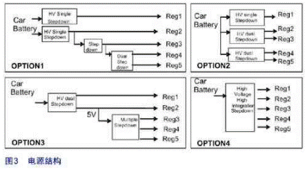
A two-way output controller with an external MOSFET can provide the same PCB layout flexibility as the solution for easy heat dissipation. For converters with built-in MOSFETs, designers should take care not to dissipate too much heat in the same location on the PCB.
Scenario 3
This architecture converts the multi-channel high-voltage conversion problem into one high-voltage conversion and a highly integrated low-voltage conversion IC. Compared with the multi-output high-voltage conversion IC, the high-integration low-voltage conversion IC has a lower cost and is easily available in the market. If the low-voltage PMIC in scheme 3 has more than two outputs, scheme 3 will have the same defects as scheme 4.
The main disadvantage of scheme 3 is that multiple voltages are concentrated on the same chip, and PCB heat dissipation needs to be carefully considered when laying out the board.
Scenario 4
The newly introduced highly integrated PMIC can integrate all necessary power conversion and management functions on a single chip, breaking through many constraints in power supply design. However, high integration also has certain negative effects.
In a highly integrated PMIC, integration and drive capability are always contradictory. For example, when a product is upgraded, a regulator with built-in MOSFETs in the original design may not be able to meet the load drive requirements in the new design.
Cascading low-voltage converters to high-voltage converters can help reduce costs, but this approach is limited by the regulator’s on/off control. For example, if the 3.3V power supply must be turned on when the 5V power supply is turned off, it is impossible to connect the 3.3V input to the 5V power supply output; otherwise, the 5V power supply cannot be turned off, resulting in a high quiescent current IQ.
Maxim’s Automotive Power Solutions
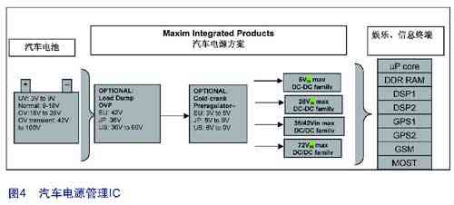
Maxim’s automotive power ICs overcome many power management issues to provide unique high-performance solutions. Power products include highly integrated multifunction PMICs such as overvoltage protection, microprocessor monitoring, switching converters, and linear regulators (shown in Figure 4). Power ICs meet automotive-grade quality certification and production requirements, such as: AECQ100 certification, DFMEA, different temperature grades (including 85°C, 105°C, 125°C, 135°C), and special packaging requirements.
The Links: NL6448BC33-74H G190EAN012


