
How to Use Digital Signal Controllers to Build Better Automotive and Electric Vehicle Systems
“By Stephen Evanczuk Traditional automotive and electric vehicle systems rely on the efficient operation of numerous Electronic devices for convenience functions and mission-critical functional safety capabilities. While these diverse applications have broad needs, fundamentally they all need to be able to operate under extreme conditions while providing reliable, high-performance real-time response. Therefore, developers urgently need a stable, robust, well-supported, and scalable platform that can help simplify the design and development of the ever-expanding automotive and electric vehicle use cases.
“
Author: Stephen Evanczuk
Both traditional automotive and electric vehicle systems rely on the efficient operation of numerous electronic devices for convenience functions and mission-critical functional safety capabilities. While these diverse applications have broad needs, fundamentally they all need to be able to operate under extreme conditions while providing reliable, high-performance real-time response.
Therefore, developers urgently need a stable, robust, well-supported, and scalable platform that can help simplify the design and development of the ever-expanding automotive and electric vehicle use cases.
This article will discuss Microchip Technology’s family of digital signal controllers (DSCs) that meet these requirements, and describe how to use these DSCs to implement essential functions in automotive and electric vehicle systems in reference designs.
Diverse design challenges require flexible solutions
Whether designing for conventional or electric vehicles, developers need to address a growing number of applications, including power conversion subsystems, in-vehicle wireless charging, digital lighting systems, and motor control systems—from relatively simple steps Electric motors are used in complex regenerative braking systems for electric vehicles (EVs) and hybrid electric vehicles (HEVs). Automakers strive to improve safety, convenience, functionality and performance in response to consumer demands and competitive pressures, and in the process, in addition to mission-critical functional safety requirements, design footprint and bill of materials (BOM) requirements is also becoming more and more important.
To meet these requirements, the industry has rapidly switched to digital solutions for nearly all vehicle subsystems.Subsystems in traditional passenger vehicles have long relied on microcontrollers (MCUs) that run four times more software code than commercial aircraft[1].
However, with increasing demand and competitive pressure, early microcontroller solutions may not meet the range of requirements that automotive designers now face. More and more electronic subsystems and associated high voltage DC/DC conversion functions require different power rails, especially in electric vehicles, which requires more sophisticated digital control capabilities. Other applications, such as in-vehicle wireless charging of mobile devices, have introduced a new set of design requirements to build multi-coil wireless power transmitters that are compatible with industry standard power receivers built into more consumer devices. Vehicle lighting design needs to consider technical characteristics such as dimming, temperature, component aging, etc., to provide brighter headlights, pleasing colors and dimming effects in the instrument panel. Finally, sophisticated digitally controlled motors are ubiquitous even in conventional cars, which clearly provides the functional basis for electric vehicles.
Microchip Technology’s dsPIC33 DSC family is specifically designed to meet these diverse requirements, with members with dedicated features. The newest member of the family, the dsPIC33C, extends the performance and functionality of the dsPIC33E and dsPIC33F DSCs for developers to use in more complex applications.
Based on a digital signal processor (DSP) core, these DSCs combine the simplicity of an MCU with the performance of a DSP to meet changing requirements for high performance, low latency, real-time capabilities, and more, while maintaining a minimal footprint and BOM. With Microchip’s extensive ecosystem of dsPIC33 development boards, reference designs and software development tools, developers can extend their designs with different members of the dsPIC33 family, providing a broad range of applications at the heart of automotive and electric vehicle systems.
Provides a more efficient hardware foundation for automotive and electric vehicle design
The software-based high-speed digital control loop is the foundation of many automotive subsystems, and Microchip’s dsPIC33C family is specifically designed to reduce latency and speed up execution of this loop. To provide this capability, these devices integrate a DSP engine, high-speed registers, and tightly coupled peripherals including multiple analog-to-digital converters (ADCs), digital-to-analog converters (DACs), analog comparators, and operational amplifiers.
Features such as the DSP engine’s single-cycle 16 x 16 multiply-accumulate MAC (40-bit accumulator), zero-overhead loop and barrel shift ensure high-speed execution of the digital control loop. Peripheral functions enable independent operation of precision control loop interfaces such as 150 ps resolution pulse width modulator (PWM), capture/compare/PWM (CCP) timers, peripheral trigger generators, and user-programmable configurable logical unit.
Packaged in packages as small as 5 x 5 mm, the devices feature a wide range of on-chip features, helping developers achieve the smallest footprint and BOM required for shrinking device size in stylish automotive systems. These devices further simplify automotive design and support a variety of communication interfaces, including Controller Area Network (CAN), Local Interconnect Network (LIN), and Digital Multiplexing (DMX) used in advanced automotive systems. Additionally, these devices are available in different memory sizes in single-core and dual-core configurations, providing the scalable solutions required for advanced automotive and electric vehicle applications.
Suitable for harsh automotive environments, these parts are AEC-Q100 Grade 0 qualified to meet the stringent requirements of under-the-hood operation and support an extended temperature range of -40°C to +150°C. Most importantly for mission-critical automotive designs, selected members of the dsPIC33 family have the required functional safety to easily meet relevant safety specifications including ISO 26262 (ASIL A or ASIL B), IEC 61508 (SIL 2) and IEC 60730 (Class B). These dsPIC33 family members integrate specialized safety hardware features, including watchdog timers, watchdog timers, fail-safe clock monitoring, random access memory (RAM), built-in self-test (BIST) and error-correcting code.
For software development, Microchip’s MPLAB XC C compilers are TüV SUD certified for functional safety, and in some cases diagnostic software libraries are available. In addition, Microchip provides relevant Failure Modes, Effects and Diagnostic Analysis (FMEDA) reports and safety manuals required during the safety certification process.
The hardware safety features and development capabilities required for functional safety certification are only part of a rich development ecosystem that supports dsPIC33-based traditional and electric vehicle designs. Based on its MPLAB X Integrated Development Environment (IDE), Microchip provides an extensive set of specialized design tools and libraries for different application areas, as described below.
To help further accelerate development with the dsPIC33 family, Microchip offers an extensive ecosystem of dsPIC33 development boards, as well as downloadable design resources including white papers, application notes and reference designs. Among these resources are several dsPIC33C reference designs that address several key automotive and electric vehicle application areas, including wireless charging, digital lighting, power conversion and motor control. In addition to demonstrating the use of dsPIC33C DSCs in various fields, these reference designs and associated software can also serve as a starting point for implementing custom designs.
Implementing Precision Digital Control Loops for Power Conversion
Control loops are at the heart of many automotive and electric vehicle applications, and one of their most critical uses in these applications is to meet the basic needs of power conversion. Efficient DC-DC conversion remains important in conventional automotive systems and is essential in high-voltage electric and hybrid vehicles. In these systems, battery voltages of 200 V to 800 V need to be safely and efficiently dropped to the required 12 V or 48 V levels to operate exterior and interior lighting, as well as power motors for wipers, windows, fans and pumps.
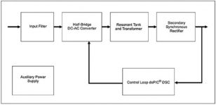
In the 200 W DC/DC LLC (three reactive elements: two inductors and one capacitor) resonant converter reference design[2]a single dsPIC33 device implements a compact digital solution for switch-mode power conversion using one of the integrated PWMs to drive half-bridge MOSFETS in the control loop (Figure 1).
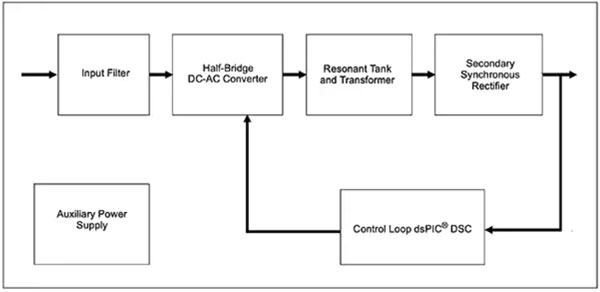
Figure 1: Microchip Technology’s DC/DC LLC Resonant Converter Reference Design relies on a single dsPIC33 DSC to digitally manage the control loop at the heart of the power conversion design. (Image source: Microchip Technology)
In Figure 2, the resonant transformer isolates the primary side high voltage (black line) of the MOSFET driver (D) from the secondary side 12 V supply (blue line) and from the 3 V supply of the dsPIC33 DSC and other analog (A) components Power isolation.
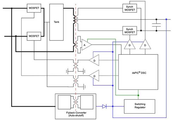
Figure 2: The dsPIC33 DSC helps simplify design and reduce part count through its specialized peripherals, where it uses integrated PWM and peripheral functions to control external MOSFETS (D) and other analog (A) components. (Image source: Microchip Technology)
In this design, the dsPIC33 uses a basic interrupt-driven software design to manage the digital control loop. The ADC interrupt is used here to obtain the output voltage used in the software proportional-integral-derivative (PID) controller. Another ADC interrupt supports temperature sensing, while the dsPIC33’s analog comparator supports overcurrent and overvoltage event detection. In fact, performing the PID control process and associated control loop management tasks leaves a significant processing margin for housekeeping and monitoring tasks, including temperature monitoring, fault monitoring, and communications, all handled by a simple firmware sequence (Figure 3).
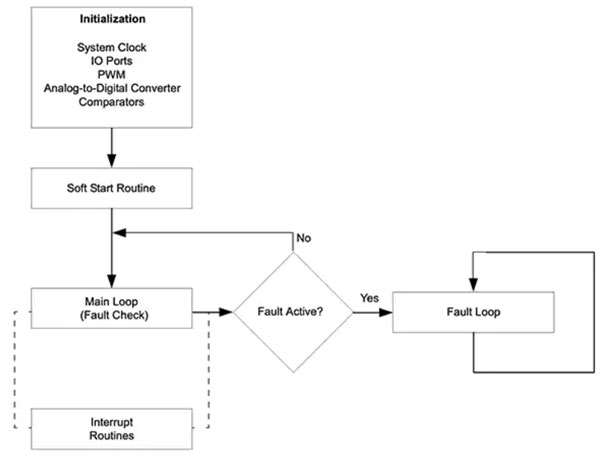
Figure 3: The dsPIC33 DSC’s high-performance DSP engine and tightly coupled peripherals enable developers to easily implement complex digital control loops with simpler code. (Image source: Microchip Technology)
For developers looking to create more specialized digital power solutions, Microchip’s Digital Power Design Kit supports the entire design process from concept to firmware generation for the target dsPIC DSC. Based on the dsPIC DSC hardware capabilities, developers use the kit’s Digital Compensator Design Tool (DCDT) to analyze control loops and use the MPLAB Code Configurator (MCC) to generate code to use optimized assembly from the Microchip Compensator Library Code function (Figure 4).
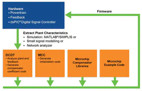
Figure 4: Developers can take advantage of Microchip’s comprehensive tool chain to accelerate the development of the core of a digital power subsystem — an optimized software-based control loop. (Image source: Microchip Technology)
Whether building standards-based devices such as wireless power transmitters or implementing more complex custom devices, designers of automotive and electric vehicle control loop applications need to implement compact solutions that support beyond baseline functions such as fault monitoring other functions. Another reference design illustrates how a single-core dsPIC33CK DSC can be used to provide a rich set of functions in another important digitally controlled power conversion (wireless power transfer) application.
Implementing Qi Compliant Wireless Power Transmitters
Qi standard by the Wireless Power Consortium (WPC) for 5 to 15 W wireless power transfer, widely adopted by manufacturers of smartphones and other mobile devices; consumers simply place their Qi-enabled device on any built-in compatible wireless transmitter surface to charge the device. Embedded in car interior surfaces or in third-party charging products, Qi wireless power transmitters provide a convenient way to charge smartphones without the clutter and potential interference associated with wired power connections. 15 W Qi Wireless Power Reference Design from Microchip Technology[3] It shows how the dsPIC33 can be used to simplify the implementation of this type of subsystem (Figure 5).
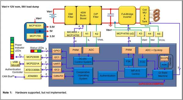
Figure 5: The dsPIC33’s integrated peripherals can work independently to accelerate critical control tasks, leaving processing headroom for other tasks such as user interface, communications, and security for more complex applications such as wireless power transmitters. (Image source: Microchip Technology)
Based on Microchip Technology’s single-core dsPIC33CK256MP506 DSC, the reference design leverages the integrated capabilities of this DSC to implement a digital control loop. Although this design is based on a full-bridge topology rather than the half-bridge topology used in the resonant converter mentioned above, the device’s multiple PWMs can easily accommodate this additional requirement.
Wireless power transmitters typically provide multiple radio frequency (RF) coils to transmit power, and in this design, the bridge inverter is connected to one of the three coils through a multiplexer (MUX). As with the full bridge inverter and voltage regulation front end, the design takes full advantage of the dsPIC33’s integrated peripherals to manage coil MUX switching.
In addition to controlling Microchip’s MIC4605 and MP14700 gate drivers, the dsPIC33 peripherals have the following functions:
・Control power indicator light-emitting diodes (LEDs) via Microchip’s MCP23008 I/O expander
・USB connectivity via Microchip’s MCP2221A USB bridge device
Supports WPC-compliant secure storage through Microchip’s ATECC608 certified devices (available from Microchip as an authorized WPC Manufacturer Certification Authority (CA))
Provides CAN connectivity with ISO 2622 functional safety via Microchip’s ATA6563 CAN Flexible Data Rate (FD) device
Additionally, the reference design uses Microchip’s MCP16331 buck converter and MCP1755 linear regulator to support auxiliary battery power.
Using this relatively small BOM, this reference design provides a Qi-compliant solution with all the key features of a wireless power system, including high efficiency, extended charging area, useful Z distance (transmitter and receiver distance between devices), foreign object detection, and support for the many fast-charging implementations used in leading smartphones. Building on this software-based design, developers can easily add features such as a proprietary communication protocol between the transmitter and receiver, as well as wireless connectivity options such as Bluetooth.
Enabling compact digital lighting solutions
The integrated capabilities of the dsPIC33 device are especially important in related automotive and electric vehicle applications, where complex functions can be added without interfering with the vehicle’s wiring. The advent of high-intensity LEDs has allowed automakers to enhance the design of exterior headlamps and interior lighting.
However, developers of these lighting subsystems often have to cram more functionality into a smaller package, while also supporting industry standards such as DMX, which provides a common communication protocol for lighting device chain control.Like the wireless power transmitter designs mentioned above, compact digital lighting[4] The solution was designed to take advantage of the dsPIC33’s integrated peripherals (Figure 6).
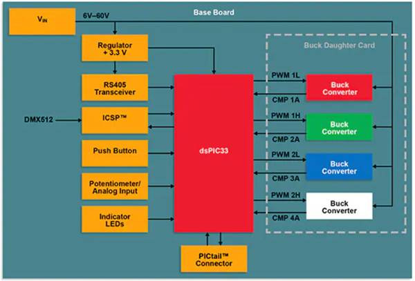
Figure 6: With Microchip Technology’s dsPIC33 DSCs, developers can implement complex designs with a minimal footprint and BOM so that functionality can be embedded in the vehicle unobtrusively. (Image source: Microchip Technology)
Like other digital power applications, this digital lighting design leverages the dsPIC33’s integrated PWM, analog comparators and other peripherals to provide a complete compact digital lighting solution. Like the design application above, this digital lighting solution relies on the processing power of the dsPIC33 DSC and the ability of its peripherals to work independently to monitor and control the required set of external devices, including power supply units, transceivers, LEDs, and more. Other Microchip design examples demonstrate the high-performance processing capabilities of the dsPIC33 DSC for handling more complex digital control algorithms and advanced motor control systems.
Implementing an Advanced Motor Control System Using a Single dsPIC33 DSC
The performance of the dsPIC33 DSC allows developers to use a single DSC to handle the core digital control loop and the execution of various auxiliary functions.In fact, Microchip’s dual motor design[5] Demonstrates the implementation of sensorless Field Oriented Control (FOC) of a pair of Permanent Magnet Synchronous Motors (PMSMs) using only a single core dsPIC33CK DSC. The key to this design is the phase-shifted PWM signals provided to the inverters for each motor control channel, Motor Control 1 (MC1) and Motor Control 2 (MC2) (Figure 7).
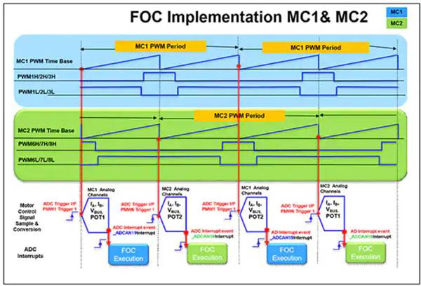
Figure 7: A single-core dsPIC33CK DSC can support dual-motor control designs with its high-performance processing capabilities and integrated peripherals. (Image source: Microchip Technology)
In this approach, the dsPIC33CK’s PWM is configured to generate the desired waveform for each motor control channel and trigger the individual ADCs at the optimal timing. When each ADC completes a conversion, an interrupt is issued, causing the dsPIC333CK to perform the FOC algorithm for that set of readings.
A single dsPI33CK DSC can also handle more powerful motor control applications. In the high-performance electric scooter (E-scooter) reference design, the dsPIC33CK is a three-phase inverter driving a brushless DC (BLDC) motor, controlling multiple FETs and Microchip’s MIC4104 gate driver (Figure 8).
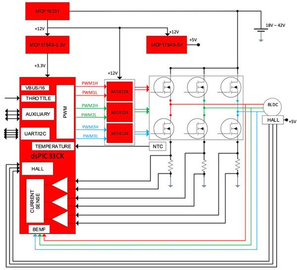
Figure 8: Using the single-core dsPIC33CK, developers can implement a robust electric scooter motor control subsystem with only a few additional components. (Image source: Microchip Technology)
Electric Scooter Reference Design[6] Both sensorless and sensor modes of operation are supported due to the ability to monitor the back electromotive force (BEMF) of the BLDC motor as well as the Hall effect sensor output. The design can use an input voltage source of 18 to 24 V and achieve a maximum output power of 350 W.
in a further extended design[7], Microchip demonstrated that regenerative braking can be added for EVs and HEVs to recover energy when the motor produces BEMF and the voltage at the motor terminals is higher than the supply voltage of the on-board battery. Here, the enhanced design uses an additional dsPIC33CK pin to monitor the signal from the brake. When braking is detected, the dsPIC33CK first turns off the high-side gate of the inverter, boosting the recovered energy above the DC bus voltage, and then turns off the low-side gate, allowing current to flow back to the supply.
Developers can extend this design with a dual-core dsPIC33CH DSC in place of the single-core dsPIC33CK to support additional features. In such a design, one core can manage the BLDC motor control and regenerative braking functions with minimal code changes, while the other core can perform additional safety functions or advanced applications. With the dual-core dsPIC33CH, motor control development teams and application development teams can work separately and have their control seamlessly integrated into the DSC for execution.
For custom motor control designs, Microchip’s motorBench Development Kit provides a graphical user interface (GUI) toolset that helps developers more accurately measure key motor parameters, tune control loops, and build on Microchip’s Motor Control Application Framework (MCAF) and motor control library to generate source code.
Epilogue
With Microchip Technology’s dsPIC33 DSCs, developers can implement a wide range of digital power designs for traditional automotive and electric vehicle applications with relatively few additional components. Supported by a wealth of software tools and reference designs, the single- and dual-core dsPIC33 DSCs provide a scalable platform for rapid development of optimized solutions for power conversion, wireless charging, lighting and motor control.
The Links: NL128102AC29-17 LM170E03-TLH3

