
Software and hardware circuit design of power amplifier switching power supply based on TMS320F28122 DSP
“Switching power supplies are gradually replacing power frequency power supplies with small size, light weight, low power consumption, high efficiency, small ripple, low noise, high intelligence, and easy expansion, and are widely used in various Electronic equipment. High reliability, intelligence and digitization are the development directions of switching power supplies. The audio power amplifier requires the power supply to automatically adjust the output voltage as the load changes, and then adjust the power to improve the dynamic performance of the power supply and reduce the internal loss of the audio power amplifier, but the current switching power supply cannot achieve this. Select TMS320F2812 DSP as the main controller of the power amplifier switching power supply, and design a low power consumption.New Smart Amplifier Switches for Larger Amplifier Systems
“
1 Introduction
Switching power supplies are gradually replacing power frequency power supplies with small size, light weight, low power consumption, high efficiency, small ripple, low noise, high intelligence, and easy expansion, and are widely used in various electronic equipment. High reliability, intelligence and digitization are the development directions of switching power supplies. The audio power amplifier requires the power supply to automatically adjust the output voltage as the load changes, and then adjust the power to improve the dynamic performance of the power supply and reduce the internal loss of the audio power amplifier, but the current switching power supply cannot achieve this. Select TMS320F2812 DSP as the main controller of the power amplifier switching power supply, and design a low power consumption. A new type of intelligent power amplifier switching power supply suitable for large power amplifier systems.
2. Intelligent power amplifier switching power supply design
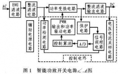
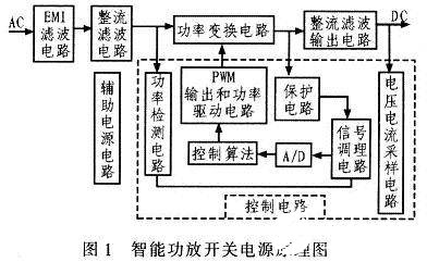
Figure 1 is a block diagram of the overall principle of the switching power supply of the intelligent audio power amplifier. The main circuit adopts the structure of alternating straight and alternating straight. The input power frequency 220 V AC circuit passes through the filter circuit, and then outputs the DC voltage through the single-phase bridge rectifier circuit. Then the stable DC voltage is output through secondary rectification and filtering; after the detection circuit samples the output voltage signal, it is sent to the control circuit, and the output voltage is adjusted by changing the output pulse width duty ratio of the control circuit; the protection circuit realizes overvoltage and overcurrent protection The power detection circuit samples the current of the conversion circuit, and when the output power exceeds 500 W, an overpower detection signal is generated to drive the control circuit and reduce the output voltage: the auxiliary power circuit supplies power to the control circuit and various operational amplifiers.
2.1 Power amplifier switching power supply module
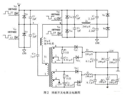
Figure 2 is the main circuit of the power amplifier switching power supply, where Vin is the 220 V AC input obtained through front-end filtering and full-wave rectification, and the voltage is 300 V. is the input voltage of the full-bridge inverter circuit. VQ1, VQ2, VQ3, VQ4 are IRFP460 high-power MOSFETs, which are used as converter switches. Since the IRFP460 type MOSFET is a majority carrier device, the switching speed is extremely fast, the typical value of turn-on and turn-off time is generally 20 ns, and it has a high breakdown voltage and a large operating current. In addition, the input impedance of the MOSFET is high, and the driving circuit is relatively simple. As long as a voltage of about 10 V is added between the gate and the source, it can be saturated and turned on. L4, C5, and C6 form an auxiliary resonant network. Considering the leakage inductance of the primary side of the transformer, the value of the resonant inductance LT is generally smaller than the actual value. Here, a non-linear saturated inductance of 1 μF with an inductance value of 34 μH is selected. Considering the high frequency pulse Transformer T1 magnetic saturation problem, the primary winding is connected in series with anti-bias capacitors, VD15 and VD16, VD17 and VD18 are full-wave rectifier diodes respectively, L1, C13, EC1, EC2 and L2, C14, EC3, EC4 are +35 V respectively and filter circuit for the -35 V output loop.
Main circuit of power amplifier switching power supply
2.2 Power amplifier switching power supply module control circuit
The control circuit takes DSPTFMS320F2812 as the core, and mainly includes the functions of generating phase-shifted pulse waveform, real-time sampling, power adjustment, overvoltage protection, overcurrent protection, overpower protection, filtering algorithm and full-bridge phase-shifting algorithm. Adopt the built-in 16-channel 12-bit high-resolution A/D conversion circuit of TMS320F2812 to realize real-time sampling of voltage and current. The minimum conversion time of each channel is 80 ns, and the input signal level range of the A/D conversion circuit is 0-3 V. After sampling, adjust the phase shift angle of the PWM waveform that drives the switch tube of the full-bridge inverter through software programming to achieve voltage regulation. At the same time, when the output voltage or current is too high or undervoltage, the DSP calls the corresponding subroutine to handle sudden abnormal events. , play a protective role. At the same time, the A/D samples the output voltage and current signal for operation, which can accurately measure the output power, and adjust the value of the relevant register of the event manager to adjust the output voltage.
The performance of the controller, such as dynamic characteristics and voltage regulation accuracy, is closely related to the regulator design. In the design of the power amplifier switching power supply, the incremental PID control algorithm is used.
The digital control in the power supply design adopts digital sampling control, that is, the control quantity is calculated according to the deviation value of the sampling time. The discrete form of PID control is:
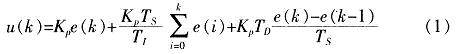
formula
In the formula, Ts is the sampling period.
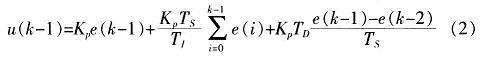
Formula (1) is a positional PID control formula. In order to increase the reliability of the control system, the incremental PID control formula is adopted, that is, the DSP only outputs the increment of the control quantity u(k), and formula (1) is the output quantity of the Kth PID controller, then (K-1 ) The output of the secondary PID controller is:
formula
Therefore, the incremental PID control algorithm is:
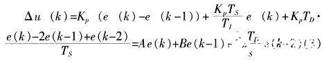
formula
formula
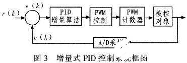
Equations (3) and (4) are the incremental PID control formulas of the control program. Compared with the positional PID control, the incremental PID control is only different in algorithm, but it only outputs the increment, which reduces the influence on the control system when the DSP misoperation occurs, and does not produce integral runaway. Fig. 3 is the realization block diagram of the PID controller based on TMS320F2812.
2.3 Software design of power amplifier switching power supply
The software design of the power amplifier switching power supply based on DSP mainly realizes the following functions:
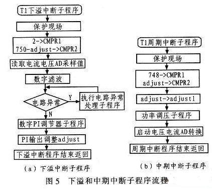
(1) The generation of full-bridge phase-shifting pulses utilizes two comparison units in the TMS320F2812 event manager to directly output circuit pulses. From the perspective of the basic principle of phase shifting, the driving between the lagging bridge arm and the leading arm has a periodic delay, and the delay angle is the phase shifting angle. It is set that the PWM1/PWM2 output by the comparison unit 1 drives the super front arm switches VQ1 and VQ3 respectively, and the PWM3/PWM4 output by the comparison unit 2 drives the lag arm switches VQ4 and VQ2. The drive pulses between the upper and lower tubes of each bridge arm are complementary and have dead zones. The drive of the fixed lead bridge arm is issued at time 0 of each cycle, as long as the time corresponding to the phase shift angle φ is delayed, and then the comparison event occurs, the result can be obtained. The driving pulse of the bridge arm is delayed, so as to realize free phase shifting in the range of 0° to 180°.
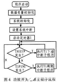
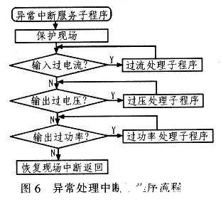
(2) Detection and protection of overvoltage, overcurrent and overpower The DSP-based power amplifier switching power supply has protection functions such as overvoltage, overcurrent, overpower and overheating. When an exception occurs. The system enters the abnormal interrupt service subroutine for processing, and locks the PWM output in time. In order to prevent malfunction, it is set to read 20 abnormal signals continuously before it is recognized as circuit abnormality, otherwise it will not be processed. The program flow of each module is shown in Figure 4 to Figure 6 .
3. Experimental results
A prototype was designed based on the previous analysis with a switching frequency of 100 kHz and output voltages of ±35 V and ±42 V. Experiments are carried out on the switching power supply of audio power amplifier based on DSP control. Under the condition of light load and heavy load, the output voltage ripple coefficient is less than 0.5%, and the output voltage accuracy is less than 0.5%. 5%.
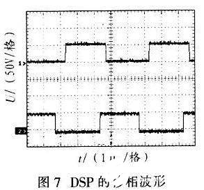
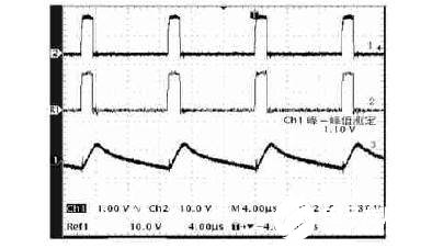
Fig. 7 is the phase shift waveform of DSP. Among them, channel 1 is the output of PWM1 of comparison unit 1, which is the leading bridge arm; channel 2 is the output of PWM3 of comparison unit 2. It is clear from Figure 7 that channel 2 lags channel 1 by about 135°. Figure 8 is the critical waveform of zero-voltage turn-on of the lagging bridge arm, the input voltage is about 175 V, and the output power is 100W. In Fig. 8, channel 1 is the waveform of the gate-source voltage Vcs of the power MOS tube, and channel 2 is the waveform of the drain-source voltage VDS of the power MOS tube. When the VDS is turned off, it is 175 V. It can be seen from Figure 8 that VDS first drops to 0, and then Vcs rises. At this time, the switch tube is turned on at zero voltage. The heavier the load, the more obvious the zero-voltage turn-on phenomenon. When the output power is 400 W and the input power is 440 W, the conversion efficiency of the full-bridge phase-shifting converter is 90.9%.
Phase-shifted waveform of DSP
Hysteresis bridge arm zero voltage turn-on critical waveform
The experimental results show that the power amplifier switching power supply based on DSPTMS320F2812 has good output waveform, less harmonic content and excellent adjustability. When the load changes in the full range, the switching power supply can maintain good output performance. The switch tube works in a zero-voltage switching state, so the power consumption of the entire power supply system is small, and it has a good application prospect in high-end high-power amplifier audio.
4 Conclusion
The DSP is used as the control core of the audio power amplifier switching power supply, which realizes the digital control of the switching power supply, overcomes the problems of component aging and thermal drift in the analog control system, and solves the problems of the single-chip control circuit load and the low calculation accuracy. The full-bridge phase-shifting circuit is used in the audio power amplifier switching power supply to effectively reduce the internal loss of the power amplifier switching power supply, so that it can be applied to the high-power audio power amplifier system.
Utilize the software and hardware resources of TMS320F2812 to realize PWM control, filtering, sampling and various system protection functions, simplify the control circuit, and improve the flexibility of power supply design and manufacturing; in addition, the controller has good controllability, easy expansion, and easy upgrade and maintenance.
The Links: M270HW02-V0 MG50N2YS1


