
EP30W audio amplifier chip output characteristics and temperature characteristics test program
“The basic connection mode and functional application of OPE30W are given in the blog post “OEP30WD audio power amplifier simple test”. What are the output characteristics and temperature characteristics of the audio amplifier chip? This article gives the test plan.
“
The basic connection mode and functional application of OPE30W are given in the blog post “OEP30WD audio power amplifier simple test”. What are the output characteristics and temperature characteristics of the audio amplifier chip? This article gives the test plan.
When the frequency of the test chip is corresponding, it is necessary to use the sine wave generating chip module AD9833. The COM2 serial port commands used are as follows:
fromtsmodule.tshardwareimport*ccloadSerial.write(b'ad9833setfrequency250 ')
The detailed reference material is: AD9833 digital signal generator module[1]
Frequency characteristic test
Since the output of OEP30W is a Class D power amplifier output, the output signal needs to be low-pass filtered before the audio signal can be obtained.Two low-pass filtering methods are used as follows: LC low-pass filtering; RC low-pass filtering
1. LC low pass filter
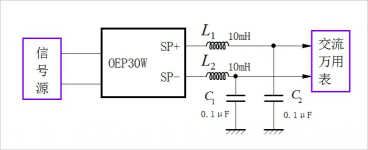
Use LC low-pass filtering for OEP30W output SP+ and SP-. As follows. The filtered signal is measured using the AC signal block of the DM3068 digital multimeter.
The capacity of the Inductor in the figure below is: and the capacity of the capacitor is:. Then the resonance frequency of the low-pass filter is:

OEP30W audio amplifier chip output characteristics and temperature characteristics test program
Measuring circuit scheme
The following is the amplitude of the output signal plotted. Since the amplitude of the input signal is fixed, this curve represents the amplitude-frequency characteristics of the entire system.
It can be seen that there is an obvious resonance peak at 5kHz, which is brought about by the LC low-pass filter.
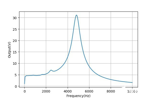
The amplitude-frequency response of the test circuit
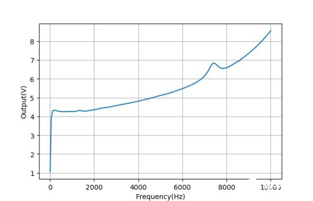
In order to reduce the influence of the resonance peak on the frequency characteristics of the OEP30W module, the capacitance value of C in the above LC is changed to 0.01uF. At this time, the resonance frequency has become 15.9 kHz.
Plotting the amplitude of the output signal changes with frequency, which represents the amplitude-frequency characteristics of the above-mentioned measurement system. Among them, below 4kHz, the amplitude-frequency characteristics of the system are very flat.
2. RC low pass filter
Use RC filter to extract the audio signal in OEP30W module.
As shown in the figure below, the inductance is changed to a resistance of 4.7kΩ. The cut-off frequency corresponding to the filter constant of the low-pass filter is equal to:
Circuit using RC filter
Plot the amplitude of the output signal as the frequency changes, which represents the frequency characteristics of the above-mentioned measurement system. The system presents obvious low-pass filtering characteristics. But it is very strange that the frequency width corresponding to this curve is much smaller than the 2127Hz corresponding to the previous RC time constant.
Response using RC filter
Modify the parameters of the previous RC low-pass filter: R=1k ohm C=0.01 microfarad
Repeat the experiment to get the corresponding input and output waveforms. It can be seen that the high-frequency component of the original PWM in the signal output by the low-pass filter at this time has a relatively obvious component.
Plot the amplitude of the output signal, as shown in the figure below, which represents the frequency response of the measurement system. At high frequencies, due to the influence of the RC filter, the high frequency gain of the system drops slightly.
Frequency characteristics of the circuit
3. Measurement conclusion
In order to reduce the impact of low-pass filtering of the PWM output on the audio signal, the effect of using an RC filter is better. The frequency response characteristic of OEP30W mode is very flat. It can meet the general high-guaranteed sound output.
Temperature characteristics
Use a thermocouple to measure the temperature of the OEP30W chip surface. The figure below shows the change in the surface temperature of the chip within 10 minutes of operation when the output frequency is 250Hz and the load is 4Ω speakers.
At this time, the working voltage of the module is 12V, and the working current is about 0.4A. The temperature rose slowly to 55 degrees Celsius after ten minutes.
Temperature curve
As the thermocouple is fixed, white plastic insulating tape is used to cover the chip, so the heat dissipation of the chip is affected to a certain extent. So if there is no measurement effect, the operating temperature of OEP30W will not exceed 50 degrees Celsius.
The Links: EP4CGX50CF23I7N https://www.slw-ele.com/6mbi450vm-170-50.html“> 6MBI450VM-170-50 POWER-IGBT


