
Design of Image Acquisition and Processing System Based on TMS320DM642 and EPM240 Chips
“At present, the cigarette packaging of major domestic tobacco manufacturers is carried out on a high-speed assembly line, with a high degree of equipment automation, complicated mechanical and electrical control, and often produce unqualified products in the production. The current solution is mainly to transfer the cigarette pack image to the industrial computer through a capture card, and apply image processing technology to detect unqualified products. This is a PC-based detection method. The existing capture cards generally do not have image processing capabilities and are mostly PCI interfaces, which are inconvenient to install and use, and do not support hot plugging and other problems.
“
1 Introduction
At present, the cigarette packaging of major domestic tobacco manufacturers is carried out on a high-speed assembly line, with a high degree of equipment automation, complicated mechanical and electrical control, and often produce unqualified products in the production. The current solution is mainly to transfer the cigarette pack image to the industrial computer through a capture card, and apply image processing technology to detect unqualified products. This is a PC-based detection method. The existing capture cards generally do not have image processing capabilities and are mostly PCI interfaces, which are inconvenient to install and use, and do not support hot plugging and other problems.
This article proposes an embedded acquisition system with preliminary image processing functions composed of TI’s high-performance DSP processor TMS320DM642, video decoder and Altera’s new CPLD EPM240. The USB interface is used to transmit the detected unqualified product image information to the industrial computer in real time, for the production staff to further analyze and count the problems in the packaging, and to maintain the production equipment in time to reduce the production cost of the enterprise.
2 System design
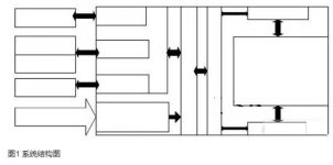
The video port of the DSP processor receives the video data output by the video decoder, collects a frame of image, and moves the data buffered in the video port FIFO to SDRAM through EDMA. After image processing, it is judged whether there are errors such as turn-up, misalignment and breakage of the pulling wire. To remove cigarette packets, the industrial computer sends a read request to wake up the USB chip EZ-USB SX2 (CY7C68001), and the DSP starts EDMA to transfer the image in the SDRAM to the USB FIFO (EP6). The system block diagram is shown as in Fig. 1.
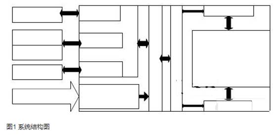
Figure 1 System structure diagram
DM642 is a fixed-point digital signal processor for multimedia applications launched by TI. The design main frequency is 500~720MHz. It adopts C64x core and 2-level memory structure. At the same time, the chip also integrates a video port (VP) and an external memory interface ( EMIF) and other rich resources. The unique EDMA of DM642 is responsible for the data transfer between the on-chip L2 memory and other peripherals. EPM240Z is the latest MAX II Z series CPLD launched by Altera. This series uses a non-volatile embedded Flash process and an innovative look-up table (LUT) logic structure, breaking through the cost and power consumption limitations of traditional macro cell devices. On the basis of the MAX series, the power consumption is only one-tenth, while the capacity has been increased by four times, and the performance has been doubled.
EZ-USB SX2 (CY7C68001) integrates a USB2.0 transceiver, a serial interface engine SIE, a 4KB FIFO, and a selectable 8-bit or 16-bit bus mode. The on-chip SIE can complete most of the USB protocol operations, which simplifies the user setting code, but because it does not contain a microprocessor, the application layer protocol is implemented by DSP programming.
3 USB communication interface hardware design
SX2 is configured in the CE1 space of DM642 in the system, and the address space of the four endpoints (EP2, EP4, EP6, EP8) is 0xA0000000 “0xA0001BFF. The address space of the control interface (EP0) is 0xA0002000” 0xA000203F. CY7C68001 and DSP use asynchronous reading and writing to complete the exchange of data and commands between the two. The interrupt signal occupies the external interrupt EXT_INT5 of DM642. The four status signals (READY, FLAGA, FLAG and FLAGC) and the wake-up signal are respectively configured in the USB status register (USB_STS) and the USB wake-up accumulator (USB_WAKEUP) in the EPM240G. EPM240G occupies the CE1 space of DM642, the address range is 0x9A080000 “0x9A080020. The interface circuit is shown in Figure 2.
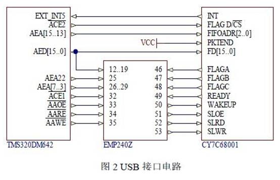
The main interface signals include control signals, data bus and address bus.
Control signal: USBINT: interrupt signal. Provided by SX2, SX2 has six interrupt sources. When an interrupt occurs, the DSP reads the data bus and obtains the interrupt flag bit to determine which interrupt has occurred.
FLAGA, FLAGB, FLABC: status signals. Provided by SX2, which respectively reflect the status of the currently selected FIFO, programmable, full, and empty.
CE1, CE2: Chip select signal. Provided by DSP, select CE1 or CE2 space.
OE, RE, WE: Output enable signal, read enable signal, write enable signal. Provided by DSP.
Address bus:
AEA22, AEA[15..13]AEA[7..3]: address bus. Provided by DSP, set the peripheral address.
4 USB communication interface DSP end software design
The software of the DSP image acquisition and processing system includes device drivers and client applications. The system software is developed on the basis of TI DSP/BIOS operating system, as shown in Figure 3. DSP/BIOS is the core of the entire DSP system software. Each low-level device driver completes hardware drive and management, and provides a unified interface to the upper layer; each application task module completes the corresponding application functions, and DSP/BIOS provides real-time task scheduling Support with the operating system. VP driver and USB driver are the underlying drivers of the DM642 video port and the EMIF port communicating with SX2 respectively, which complete the hardware abstraction and configuration management of the corresponding hardware peripherals.
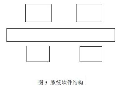
The device driver in DSP/BIOS consists of two layers. The upper layer is a class driver. Its typical function is to provide multi-threaded serialization and synchronization of service requests. In addition, it also handles the management of device instances. This layer has nothing to do with drivers. It is a part of the modules integrated by DSP/BIOS itself. It mainly includes three types of driver models: SIO, PIP and GIO. This system uses GIO drivers. The lower layer is the mini driver. The GIO driver uses the micro driver related to the specific device to operate the SX2 to realize the function of sending and receiving images of the host application. The configuration process of SX by the micro-driver is shown in Figure 4.

5 USB communication interface host-side driver design
Compared with the traditional PC bus (such as PCI bus) device driver, the USB device driver does not directly talk to the hardware. These tasks are completed by USBD.SYS provided by Microsoft. The main job of the USB device driver is to translate client software requests into transactions that USBD.SYS can execute. The USB device driver mainly completes the following functions: discover, configure, and close the USB device.
The USB device driver provides functional interfaces to the host application, such as functions like Ezusb_Creat(), Ezusb_Close() and so on. The application calls the function Ezusb_Create() and returns the only Windows handle before calling other functions of the driver. The application program realizes the access to Ezusb_Create() by calling the standard Win32 API function CreateFile(). Control and data transmission interface. The application uses the API function DeviceIoControl() to perform such operations. The driver converts this function call into an IRP with IRP_MJ_DEVICE_CONTROL function code. Operations such as reading and writing FIFO data and endpoint0 are all done through asynchronous IO.
6 Conclusion
The DM642 image acquisition and processing system with USB interface designed in this article, on the one hand, makes full use of the powerful processing capabilities and rich peripheral functions of DM642, and on the other hand uses the new architecture of the MAXIIZ series CPLD to effectively reduce the power of the system. Consumption. In terms of software, with DSP/BIOS as the core, the firmware program of USB is realized, and the device driver of USB is developed on the host side. The embedded image acquisition and processing system is designed for packaging inspection on the cigarette production line, and basically meets the needs of online inspection of cigarette rod packages.
The Links: NL10276BC24-21F QM75DY2H


